Rear Lift Strut Fittings
A lot happened today. I received the correct AN6-20A bolts from CubCrafters at the end of last week so I started today by installing one in the necessary spot in the rear lift strut fittings. After that nut was snug I went back and torqued all of the hardware which finally finished section 4 of the manual1.
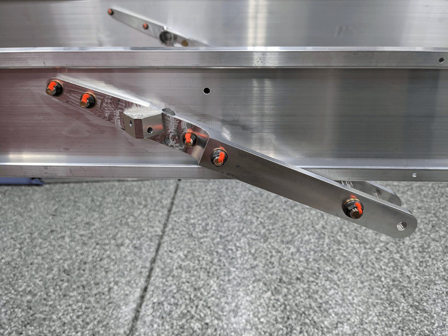 Torqued and finished rear lift strut fittings
Hinge Blocks
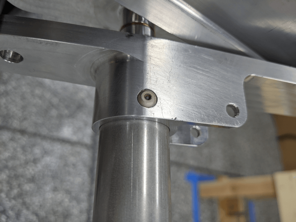
Update on the washer between the rear hinge blocks: while I was waiting for the correct bolts to arrive, I spent some time looking at pictures provided by CubCrafters. In several of the pictures you could see that the washer between the rear hinge blocks was in place even though no bolt was installed. This is exactly the condition mine is in and means that this is the intended state.
I also realized that, even though I reamed and torqued the bolts in the front hinge blocks with a 5/16” bolt in the top hole, the fit was too snug to re-insert it once it was removed. The manual addresses this2 by telling you to test fit a 5/16” bolt in the hole after the other bolts are torqued. If it doesn’t fit then the manual allows pulling the reamer through one more time. Since a bolt didn’t fit through in my case, I went ahead and pulled the reamer back through so that the fit is now correct. Once this was done all of the hinge blocks and lift strut fittings were finally done and I could move on.
Inserting the Tubes into the Fittings
Since I already completed section 5 (gluing the double ribs together), I was now able to move on to section 63. This involved inserting the tubes into the front spar fittings with the front spar laying on its side (so the tubes were sticking up into the air) and then laying the rear spar on top and lining everything up. Martha helped me with this step before she went into work.
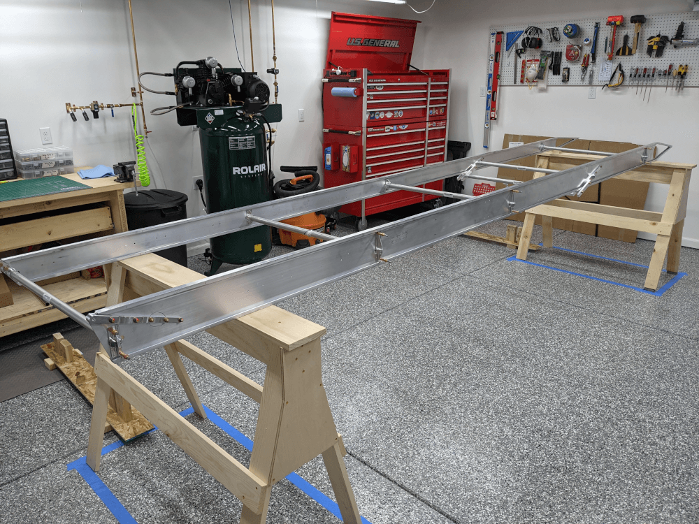 Tubes installed
The manual then instructed that you rivet the two tubes inserted into the lift strut fittings in place. This required match drilling two holes in the end of each (using a #30 bit) for a total of eight holes that would receive rivets. The rivets used were CherryMAX CR3213-4-4 rivets. These are blind (pop) rivets that have a steel stem and are stronger than typical blind rivets. I used a clamp to hold the spars together (and the tubes fully in their fittings) and drilled all of the holes (inserting clecos as I went). I then began inserting and pulling the rivets.
CherryMAX rivets are very sensitive about being pulled correctly and I knew that holding the gun perpendicular to the rivet (so you don’t pull at any sort of an angle) was extremely important. I had tried this with some scrap aluminum in the past and it seemed to work out just fine so I thought that I had the technique down. Unfortunately, due to a misunderstanding about what a properly set rivet should look like, I didn’t realize that most of them appear to be incorrect until after all of them were installed. According to the process manual from Cherry Aerospace, the stem should be flush (or very close to flush) with the rivet head when set correctly. Unfortunately, the stem broke off below the rivet head on most of my rivets meaning that they will need to be drilled out and redone.
It is fairly common to need to drill out and replace rivets when building an airplane so this shouldn’t be a problem. The major annoyance here comes from the fact that the spars will need to be separated again so that the drilled out rivets can be removed from the tubes (otherwise they would just rattle around in there). The CherryMAX manual provides the process for drilling out these rivets but it is more difficult than standard solid rivets due to the steel stem. You are supposed to be able to drill down into the center enough to destroy the locking collar that holds the stem in place. Then you should be able to use a punch to push the stem out the back before finally drilling into the head just enough to break it off. Finally, you can push the remainder of the rivet through the hole with a punch.
I tried this removal process on the practice rivets I had pulled earlier. Those rivets were actually pulled correctly so it wasn’t exactly representative of what I will need to do but it definitely wasn’t easy. I’m not as confident with this process as I’d like to be so I’m planning to contact CubCrafters to see if they have any tips.
 Incorrectly pulled CherryMAX rivet
Match Drilling Blocks and Fittings
Section 74 of the manual instructs the builder to match drill the remaining holes in the fittings and blocks that were cleco’d in place earlier using a #30 drill bit. Most of the blocks and fittings are then supposed to be installed with AN470AD4-8 solid rivets. I went ahead and drilled/deburred the remaining holes but was unable to install the rivets because it wasn’t clear which ones were meant to be used. The kit comes with rivets labeled MS20470AD4-8 which, according to Dave Embry’s build tips, are the correct part to use. I want to double check this though because 35 of these rivets are supplied but 56 total are needed between the two wings based on my understanding. This is something else I am planning on contacting CubCrafters about.
Trimming the First Double Rib
Since I couldn’t do any more on sections 6 or 7 I decided to go ahead and prepare for section 8 (installing the center ribs) by trimming the #1 rib to fit around the rear hinge-block bolt head, as instructed5. I cut this hole out using a nibbler in order to avoid deforming the aluminum. Unfortunately, I nibbled on the wrong side of my line and added a bit of a step to the cutout. This is a very small cutout but I’m going to confirm that this is okay with CubCrafters as well just to be safe.
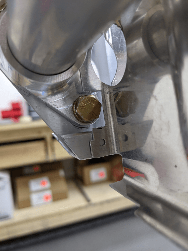 Rib cut out around bolt head
Wing Manual (Extended Fuel), CCEX-004 Rev. 2.02, Pages 46-50 ↩
Wing Manual (Extended Fuel), CCEX-004 Rev. 2.02, Page 44 ↩
Wing Manual (Extended Fuel), CCEX-004 Rev. 2.02, Pages 53-56 ↩
Wing Manual (Extended Fuel), CCEX-004 Rev. 2.02, Pages 57-59 ↩
Wing Manual (Extended Fuel), CCEX-004 Rev. 2.02, Page 63 ↩