Trammeling
Today Craig came by to help me with the wing build and we mostly tackled section 151 of the manual which involves squaring (trammeling) the wing. This is a critical step because it affects the aileron fit, affects the wing fit on the fuselage, and is when you really make the wing structure rigid.
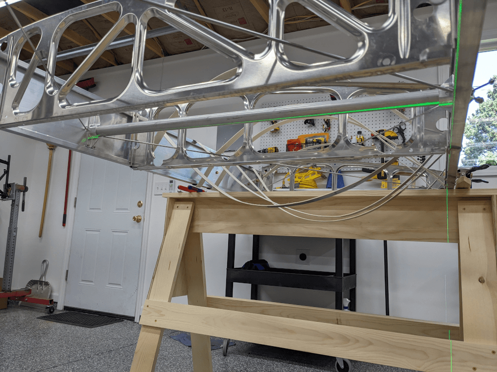
The basic idea of trammeling is that the wing has four “bays”, each with a pair of diagonal drag wires in between a set of drag tubes. The goal is to get each bay square and then tighten the drag wires to keep it that way. With tension set, these wires form a couple of triangles with the tubes (an “X” of wires between parallel tubes) and create a rigid structure. In order to do this right, you need to focus on squaring one bay of the wing at a time starting at the inboard end and working out.
Preparation
Before we could start actually trammeling, we had to make sure the sawhorses were still level and the correct distance (151”) apart. These parameters, combined with the 1” block under the aft spar, set the wing washout (twist) which is important to get right. We cut a length of string to measure 151” and used that to double check the sawhorse spacing. Once that was done, we moved the spars off the 1” block and made sure that the first and last tubes (over the sawhorses) were both level. This meant that everything was setup correctly so we put the rear spar back on the 1” block. Finally, we needed to loosen all of the drag wires so that they had plenty of play. This allowed the spars to move freely so we could set them to a square position.
First Bay
We started actually trammeling by squaring the first bay relative to the #2 drag tube (per the instructions) using a framing square that I modified per the manual (so that it would fit). By squaring both spars relative to the #2 tube we can ensure that the inboard positions of the spars (where they attach to the fuselage) are also square. If this inboard section isn’t square then the wing mounting holes in the hinge blocks may not line up with the fittings on the fuselage.
In order to square the first bay we first placed the framing square up against the #2 drag tube and the rear spar. We moved the spar back and forth to get it square and then verified that the front spar was also square with the tube. After this was done, we made both of the drag wires in the first bay finger tight. Then, alternating between these two wires, we tightened them with a wrench a bit at a time in order to evenly tension them and keep the wing square. The first bay uses one thick wire and one thin wire and they each have a different number of threads per inch. One of the tips for this section to keep even tension on the two sets of wire is to tighten the thin wire a half turn and the thick wire 3/8th of a turn at a time.
With the slack taken out of the wires, we used a Sharpie to mark a dot on the thick drag wire 1/2” from where the 2 wires crossed. We then used a small digital fish/luggage scale to pull the small wire over to this mark and make sure that the 1/2” of deflection took 13-15 pounds of pull force. We were still a bit light at first so we put a dot on the top of each drag wire (so we could see if they were spinning instead of tightening) and then gripped them with plier wrenches in order to keep them still (the plier wrenches don’t have teeth so they didn’t mar the drag wires at all). We tightened the wires and kept checking the scale until we had the right amount of tension.
At this point, we checked to make sure the spars were still square against the #2 drag tube. The tube bowed a bit from the tension (the manual mentions that this is normal) so it was a bit tough to tell but we adjusted the drag wires until the front and rear spar looked about the same against the square. Because the bowed drag tube made it difficult to verify that the bay was still square using the framing square, we also used a laser cross that Craig brought to project perpendicular laser lines and back ourselves up. Finally, once we verified that everything looked okay, we checked the tension one last time and were able to move on from the first bay.
 Using a laser in addition to a square on the first bay
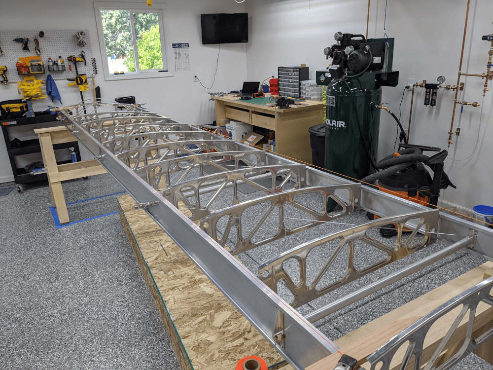
Remaining Bays
The main goal for the rest of the bays is that the rear spar makes as close to a perfect straight line as possible. This is because the machined tail ribs attached to the rear spar hold the aileron and if it isn’t straight then the aileron won’t fit right and will bind instead of moving freely. The best way to do this is to stretch a string across the rear edge of the rear spar. You want this string as closely lined up with the edge of the spar as possible and slightly above it. We used a few wooden garden stakes I had to hold the string above the spar and some 2” spring clamps to hold the ends in place. An important lesson we learned here was that you really just want this string stretching across the bays you have already trammeled (so starting at the wing root) and out to the outboard end of the bay you are currently working on. That is because you need to move the spar back and forth to keep the edge aligned with the string. If you start with it stretched all the way to the end then you are basically trying to get all of the bays square at the same time instead of just the one you are focusing on.
 The string lines set up to provide a reference to straighten the spar
The best way to make sure that the edge of the spar is aligned with the string is to place a plastic ruler (so it doesn’t scratch the aluminum) on the face of the spar so that it sticks up past the string. We aligned this so that the string just barely didn’t touch the ruler on the ends and then straightened the spar to keep this same distance throughout. Once that was achieved we could finger tighten the nuts on the drag wires in that bay, set the tension as previously described, and then move to the next bay outboard. This whole process took us a little while to perfect but we got the hang of it by the end. The next wing we do (Craig’s) should go significantly faster.
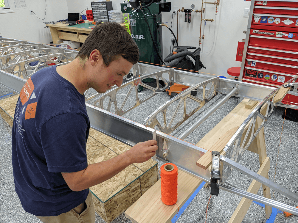 Checking the gap between the edge of the front spar and the string line
We primarily focused on straightening the rear spar with the string line since it is the critical one and what the aileron mounts to. In addition, since the spars are held a constant distance apart by the ribs and drag tubes the front spar should be straight as long as the rear one is. In order to be thorough, we did set up a string line for the front spar in the same way we had for the rear and found that it was also nice and straight.
Checking the Rear Spar
Section 151 calls for the builder to use Loctite #271 on the outer jam nut of each drag wire (except for the inboard nuts on the first bay since they will be temporarily removed later). However, before that is done, the spar should be checked per section 162 of the manual. This section has the builder temporarily install the center aileron hanger (attached with a single AN3 bolt through the spar web just above the lift strut blocks) and then install the aileron with 1/4” bolts. If everything is straight then it should go on without having to force it and move nicely without binding.
We pulled out the left aileron and installed the bolts through the machined tail ribs and into the two ends which went in really nicely. We did have to lift the center aileron hanger into position a bit because it wasn’t very tight yet and was sagging in the middle. Once lined up, this bolt went in nicely too. At this point, we were able to move the aileron up and down (which was extremely satisfying) without it binding or taking much force at all. In fact, the motion felt very smooth. We were pretty sure this was what we were shooting for but did spend a little extra time verifying that this was correct because of the center hanger not lining up right away.
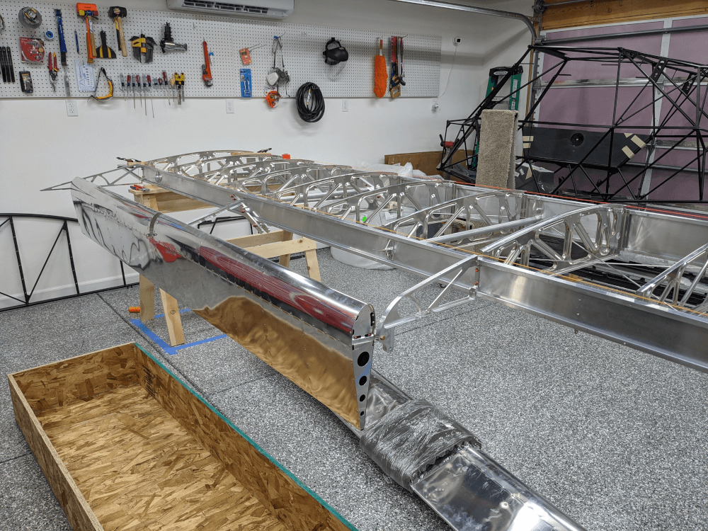 Aileron temporarily installed to check the rear spar
After we confirmed that everything was looking good we removed the aileron and put it back in its crate under the wing for safe keeping. We decided this was enough for the day so tomorrow we will just need to apply Loctite to the drag wire jam nuts, cut off a bit of extra drag wire that is protruding past the nuts and getting a little too close to the center aileron hanger, and reinstall/Loctite/torque the bolt in the center aileron hanger in order to finish sections 15 and 16. After that we can move on to 17 - installing the diagonal cross tube.