Tonight I worked on installing the capstrips on the tops of ribs #1 and #3. These capstrips form the inboard and outboard sides of the fuel tank bay and have nutplates that will eventually hold screws that hold the fuel tank cover on.
Rib 1 Capstrip
I had checked with CubCrafters about the forward most hole in the rib #1 capstrip since it was extremely close to the edge of the rib (See the build log entry from April 10 for a picture and details). Pete checked some factory built planes and told me that they don’t install that rivet in the factory and that it should be left out. He sent me some pictures and said that they would include that in the next manual update.
Now that I knew that, I covered the hole with tape (so I wouldn’t accidentally drill it) and positioned the capstrip back on the top of rib #1 making sure that it was flush with the back of the tail rib and flush with the outboard side of rib #1. I placed spring clamps all down the capstrip to hold it in place. With the capstrip lined up, I match drilled all of the #30 holes from the capstrip into the rib (including the 2 in the tail rib) and also drilled the hole for the stainless steel rivet in the flap false spar.
 The holes drilled and cleco’d in the top capstrip for rib #1
With that done, I removed the capstrip, deburred all the holes, and then reinstalled it. I also covered the cleco for the hole where the stainless steel rivet would go with tape so I wouldn’t accidentally countersink it. After that, I went hole-by-hole countersinking and pulling the appropriate countersunk CherryMax rivet. I also installed the stainless steel rivet in the most rearward hole (in the false spar). I recently bought a compressed air manifold (which I attached to my rolling shop cart) and it was extremely helpful during this step. I used it so that I could have both the drill (with the countersink) and the rivet puller attached to air at the same time. This let me progress through these rivets very quickly as I could countersink a few holes, pull the rivets, then repeat.
After the rivets were all pulled I match drilled the center #20 holes for the nutplates. I used a drill stop but set it a little longer than necessary and “pulsed” pressure while drilling to try to get a cleaner hole. I especially tried to use light pressure as the drill bit broke through the back of the hole. This was necessary because it becomes harder to drill a clean hole in sheet metal without the bit “catching” as the hole gets bigger. On this same topic, the manual only called for #20 holes but Dave Embry’s tips say to actually drill them to #10. This gives you more wiggle room with the nutplates when eventually installing the tank cover. Dave said he had checked with the factory and that is what they are doing now but I double checked myself. The response I got confirmed what Dave was saying so I decided to go ahead and enlarge them to #10. Because of the problem I mentioned with drilling large holes in sheet metal, I used a #10 reamer to enlarge the holes (inserted straight through from the top using my electric drill on low speed) which worked well. Once that was done I match drilled all of the #40 holes for the nut plate rivets and then used the rivet squeezer (with flat squeezing dies attached) to squeeze the rib flat where the nutplates would go (also from Dave’s tips). I did learn that something soft (like a piece of cork that was used for padding when the kit was shipped) needed to be placed between the squeezer and capstrip to prevent it from marring the finish. This is purely cosmetic but is a good idea to do.
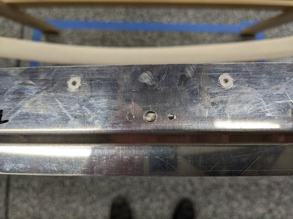 The holes drilled for a nutplate in rib #1’s capstrip
Rib 3 Capstrip
With the rib #1 capstrip done except for installing the nutplates, I moved on to rib #3. The capstrip here is supposed to be oriented with the nutplate holes facing inboard (towards the fuel tank) and with the first nutplate hole lined up with the corresponding nutplate hole on rib #1. The easiest way to accomplish this was to put it in approximately the correct location and then use a ruler laid on top of the capstrip to measure back to the spar (and then to make sure this measurement was the same measurement as that on rib #1). A straightedge held vertically against the spar made it easier to tell where the measurement was rather than trying to eyeball it (since the capstrip, and therefore the ruler, passes several inches above the spar). Once the capstrip was in the correct place and clamped down I used a long straightedge across the center of the first nutplate hole in each rib to verify that they were lined up. This straightedge looked parallel to the spar and the measurement from it to the spar was consistent throughout its length.
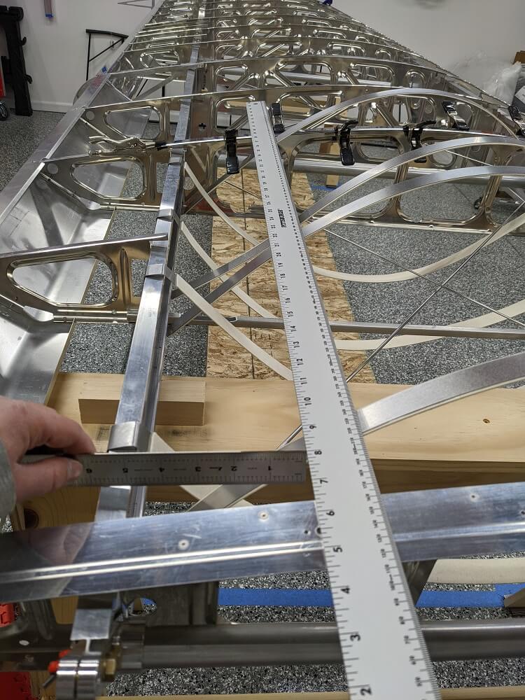 Checking to ensure the capstrip on rib #3 is lined up with the capstrip on rib #1
With the forward and backward position taken care of, I then made sure the capstrip was positioned correctly side-to-side. The manual calls for it to be centered but Dave Embry mentions that you might want to cheat inboard slightly so that the nutplates have space to fit. I measured the distance from the center of the double rib (the vertical portion) to the edge of the capstrip and then compared this to where the nutplate would be (when laid on top). I determined that he was right and that it wouldn’t quite fit if it was perfectly centered. Instead, I cheated inboard so that the capstrip stuck out approximately 19/32” past the middle of the center rib. I had determined this is about what was needed in order to get the nutplate to fit and it also gave the most forward rivet (once again in the skinny part of the rib) more edge clearance. This ended up with about 1/16” more overhang than on the outboard side but was still fairly centered.
With the position verified and the capstrip clamped in place, I repeated the same procedure as on rib #1 to install it. I drilled and cleco’d all of the holes, deburred both parts, reinstalled the capstrip, countersunk the holes, installed the CherryMax rivets, drilled the center holes for the nutplates, reamed these center holes, and then finally match drilled the #40 holes for the nutplate rivets. One other thing to note when doing this is that the reamer can easily go through the hole and take a small amount of material off from the rib below. Since there is no drill stop (like on the #20 bit) you have to be extra careful to avoid doing that. I had a couple instances where that happened but fortunately they won’t affect the rib in a meaningful way.
At this point, all that is left to do for section 231 of the manual is to countersink the holes for the nutplate rivets and then install the nutplates.
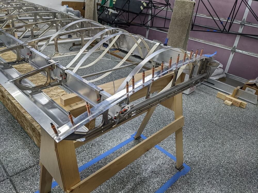
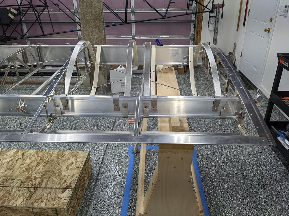 Capstrips installed on the tops of ribs #1 and #3
Wing Manual (EX-2/EX-3) CK-KM301 Rev B, Section 32 ↩