The first thing I did today was cut out the leading edge skin for the stall warning horn per section 591 of the manual. After marking the position in Sharpie with the template provided, I drew an “X” through the large center hole and used a #30 bit to drill out the center. This gave me a pilot hole so I didn’t have to worry about the stepped bit walking on the curved surface. With that done, I used the stepped bit in my battery-powered drill to enlarge the hole until it was almost the size of the cutout. From there, as the manual dictated, I used a nibbler and files to finish enlarging the hole to the prescribed size.
From there, I moved on to the slots and ended up using a #20 bit to drill each end instead of the 3/16” that the manual called for in order to give myself a bit of leeway for being off center. It was relatively easy to use small files to remove the rest of the material from the slots once the end holes were drilled. After that was done, I test fit the stall warning horn, made some slight adjustments to the slots, test fit it one last time, and then cleaned up all of the edges to make sure there were no burs/sharp bits.
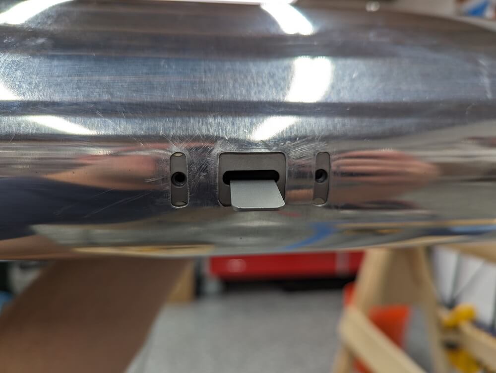 The stall warning horn being test fit in the cutout
Once the stall warning cutout was done, I moved on to installing the fuel tank ground cables per section 612. Each fuel tank (inboard and outboard section) has a tab pre-attached for the grounding wire and the other end attaches to the adjacent rib. The manual is not specific about where to drill the hole in the rib so I took that to mean it didn’t matter much and did my best to match the diagram. The manual also didn’t specify a drill size but, based on the hole size in the fuel tank tab, I went with a #30. This caused the screws to sort-of cut their own threads in the ribs (and the tank tabs, which were pre-drilled) as they were screwed in but, by snugging the screw in the hole before snugging the nut, I was able to get everything tight. I also wrapped a bit of friction tape around the wires where they passed by edges of the ribs. The manual didn’t specify to do this but I figured a little extra chafe protection couldn’t hurt.
Finally, I tried installing the aileron cable per section 612. After “completing” this, I realized that the outboard pulley cage wouldn’t pivot on its mounting bracket and that the inboard pulley wouldn’t turn. The problem with the inboard pulley was that I missed bushing SC15000-041 and will therefore need to install the entire pulley. I discovered this when looking at Dave Embry’s build tips to see if he mentioned it or the outer bracket. I also discovered that he recommends greasing the pin on which the outer pulley rotates with some white lithium grease so I’ll need to take that apart too. I think I’ll just completely remove the aileron cable and try it again. Fortunately, that is easy to do so no harm done.