Aftercooler
The first thing I finished up today was getting the aftercooler hooked up to the compressor. An aftercooler is just a cooler that cools the air after it has been compressed. This is necessary because compressing air raises its temperature significantly. If that air cools in the compressed air lines or in the tool then water droplets can form (since cooler air can’t hold as much moisture as warm air). This water can damage tools but is especially detrimental when trying to use the air for painting (which I will be doing).
Cooling the air immediately means that it won’t be able to cool as much in the air lines and therefore won’t cause as much condensation in them. This also makes the in-line moisture separator more effective because by the time air reaches it more of the water content will be liquid that can be separated out.
Compressor Attachment
The cooler I ended up using was a Derale 15300. This is meant to be used as an engine oil cooler but it is often used as a compressor after cooler and works well for that job. One of the downsides, however, is that it doesn’t come with a mounting bracket and there are no mounting holes.
I decided to mount the cooler to the compressor belt guard since the flywheel has a fan built-in (to cool the cylinders) that can do double-duty by moving air through the aftercooler as well. This seems to be a common mounting strategy as well. Craig purchased the same compressor and aftercooler so we decided to try to figure out how to tackle it together.
First Attempt
Our first idea for mounting the cooler was to use a couple pieces of aluminum running vertically on the compressor side of the belt-guard with holes drilled in the top and bottom. We were then planning on using a couple more pieces behind the after-cooler. We could then tighten bolts running between the front and rear pieces so that the after cooler would be “pinched” in-between.
This seemed like a good strategy and we bought all of the required parts; however, it wasn’t as simple as we thought it would be. The bottom of the belt-guard was closer to the tank than we thought so when we began trying to get things mounted to Craig’s compressor we realized that there wasn’t enough clearance for the bolt head. We tried bending a step in the aluminum and considered some other options before I realized there was a better way.
Second Attempt
I realized that a pipe clamp would do exactly what we were trying to do and that it would make it much simpler. The metal for pipe clamps is very thin and could easily wrap around the belt-guard and be tightened to hold the aftercooler. We both liked this idea so I ordered some 12” pipe clamps and we cut some of the angle aluminum that we had bought for the first attempt to protect the aftercooler fins from the pipe clamps. We had also bought some neoprene to isolate the aftercooler from the compressor so we cut some squares out of that together as well.
Once the pipe clamps arrived it only took me about 15 or 20 minutes to get everything hooked up. There are thin strips of neoprene on the left and right side of the aftercooler to keep it from rubbing the belt-guard and small pieces under each corner where the pipe clamp would have contacted the compressor. This installation ended up going very smoothly and seems to hold the aftercooler to the compressor very tightly.
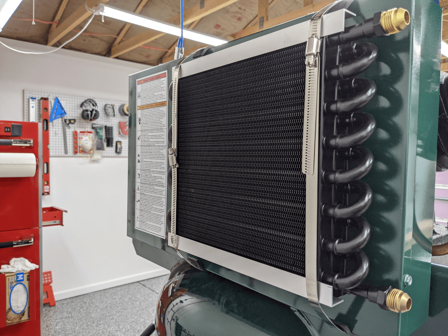 Installed aftercooler
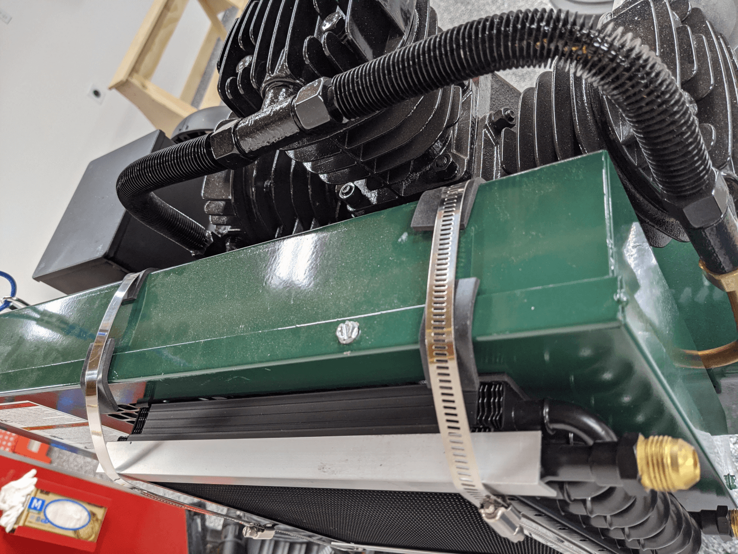 Neoprene under the pipe clamps
Plumbing
The plumbing for the aftercooler also ended up being a bit more involved than I would have thought. The belt-guard vibrates a fair bit when the compressor is operating so Craig and I decided against using copper tubing to connect to the cooler since it seemed like that could be a failure point. Instead we decided to use braided hydraulic hoses. These are rated to 1,000 PSI which is well above the 150 PSI our compressors are capable of. It is also easy to cut and add hose ends to.
The fittings on the cooler itself are male AN-8 fittings but the compressor outlet uses a 1/2” SAE flare fitting and the tank inlet uses 1/2” NPT. This meant that we were going to have to do some conversions.
To keep things simple (and so that we could use swivel fittings) we used female AN-8 hose ends on the braided hose. This allowed us to go directly into the cooler with no adapters. On the compressor outlet side, on the other hand, we had to create a 90 degree adapter using a 1/2” SAE flare coupling, a 1/2” SAE flare to 1/2” NPT elbow, and an 1/2” NPT to AN-8 adapter.
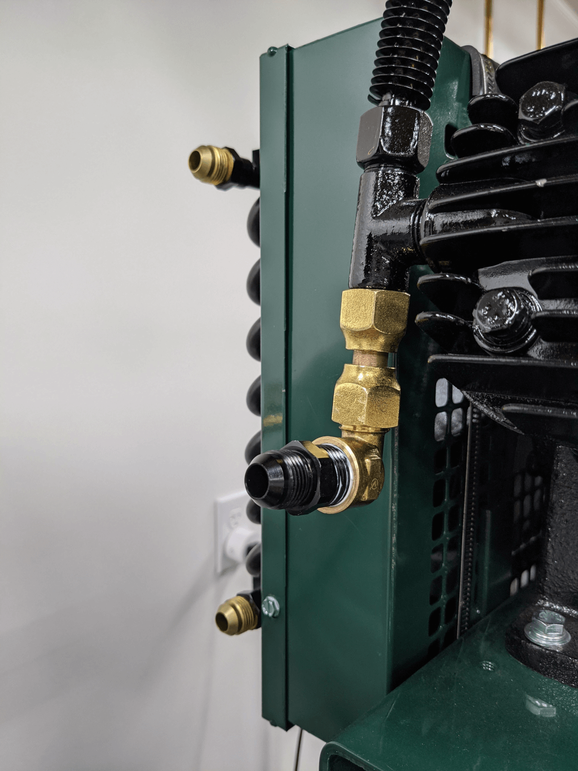 Compressor outlet adapter
The tank inlet used a 1/2” NPT to compression elbow and a compression fitting on the copper pipe. These had to be replaced with a 1/2” NPT street elbow and an NPT to AN-8 fitting. This was much simpler fitting wise but was very challenging to get to thanks to one of the compressor cylinders. Removing the old fittings and installing the new ones required using a basin wrench and some combination wrenches held at an angle.
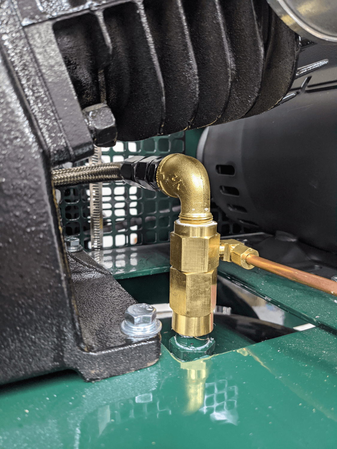 Tank fitting
Martha’s dad, Billy, once again helped me get the hoses cut (wrapped duct tape around the cut line and used a fine-toothed hack saw) and the fittings installed. This took around an hour since the fittings were a bit challenging to get to.
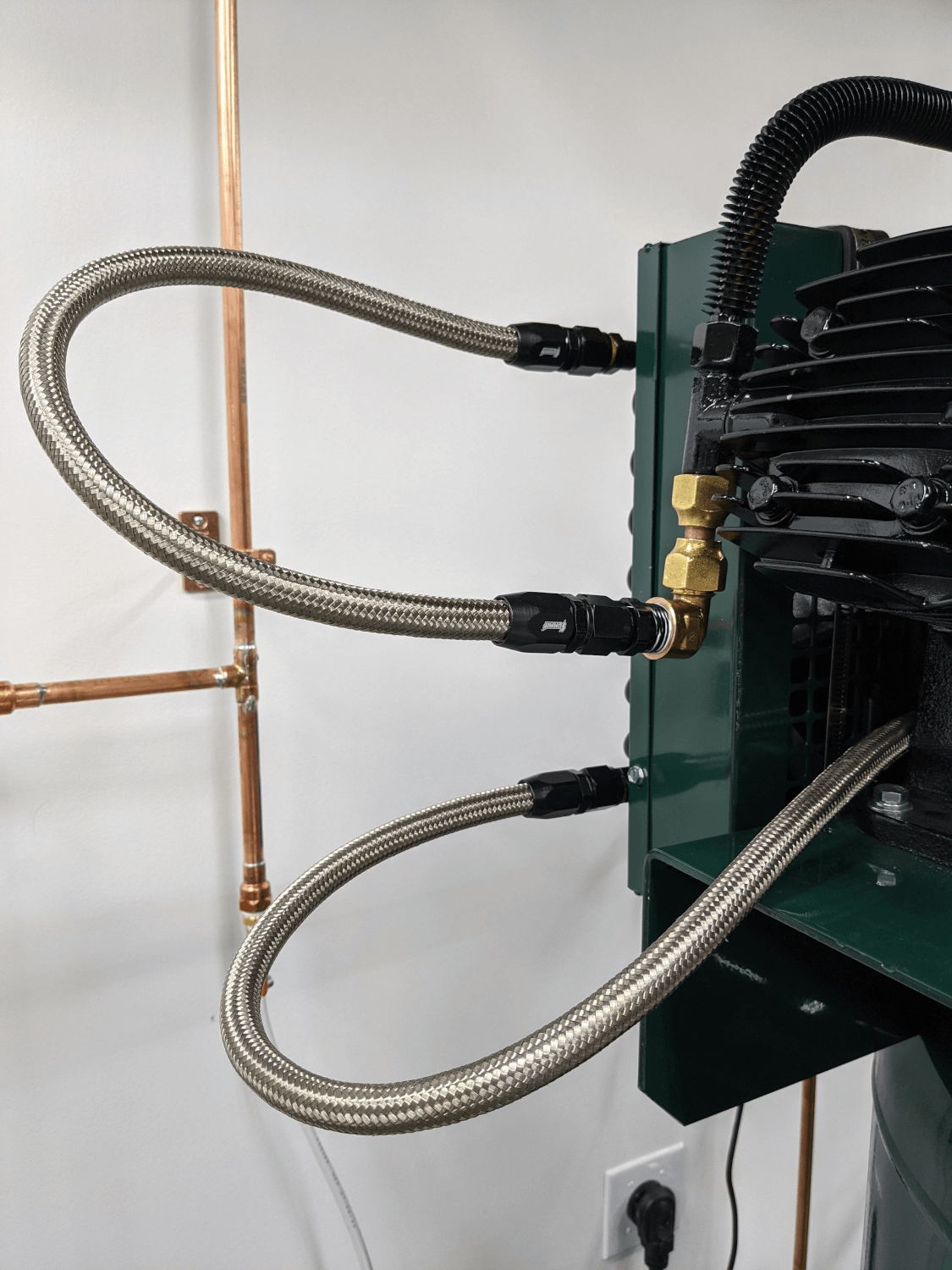 Aftercooler hooked up
Once all of the connections were made we were able to fire up to compressor to test it. Pressurizing from 0 PSI all the way to the pressure switch cutoff took about six and a half minutes, almost exactly what was required before the aftercooler installation. There was also an extremely noticeable difference between the compressor outlet temperature and the aftercooler outlet temperature so it seems like it is performing well.
Spar Fixtures
The wing manual1 directs the builder to build a set of spar holding fixtures to hold the spars vertically during the initial build stages. The only instructions given are a reference to a photo (Photo 008) so their exact dimensions are left up to the builder.
Billy helped me construct these today too and we started by cutting two 5.5” wide and 48” long pieces of MDF out of one of the leftover sheets from the shipping crate. We made these the same dimensions as the top of the sawhorses with the thinking that they could be clamped on top easily. We also thought that we would want them to run the full 48” so that we could keep the spars farther apart and therefore have more room to work.
We also cut four 6” sections of 2x4 (also left over from the crate) to hold the main spars and four 4” sections of 2x4 to hold the rear spars. We then screwed these to the MDF from underneath (using screws, you guessed it, left over from the crate) spaced appropriately for the spars. We used the first fixture as a bit of a template for the second fixture so that the spacing between the spars would be the same on both and everything would be roughly square. This took about an hour.
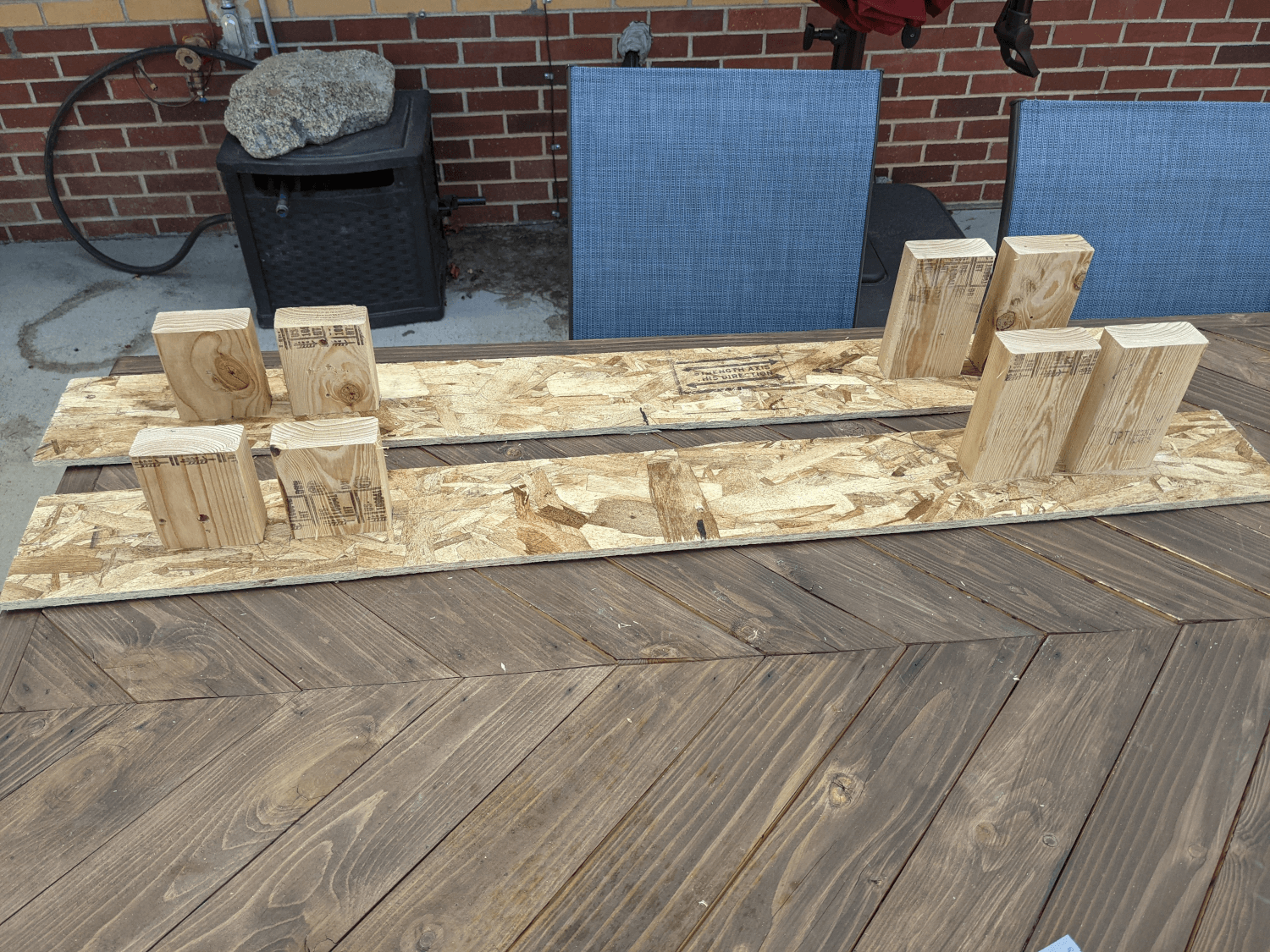 Spar fixtures
Wing Manual (Extended Fuel), CCEX-004 Rev. 2.02, Page 26 ↩