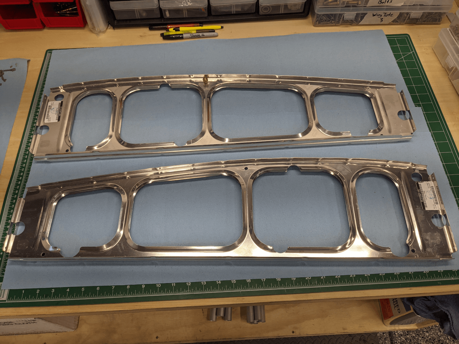
Since I am still waiting on getting the correct AN6-20A bolt for the rear lift strut fitting I decided to do some more workshop setup today.
I started by un-clamping and double checking the glued double ribs and putting them away with the rest of the left-wing ribs for now.
 Glued double ribs
After that I decided to modify the framing square as specified in the manual. This involved cutting an angle off the corner and shortening the short side. I used a cutoff wheel on my Dremel tool to cut the angle and a hacksaw to shorten the short side. I also used a file to smooth out all of the sharp edges left from the cutting.
 Modified framing square
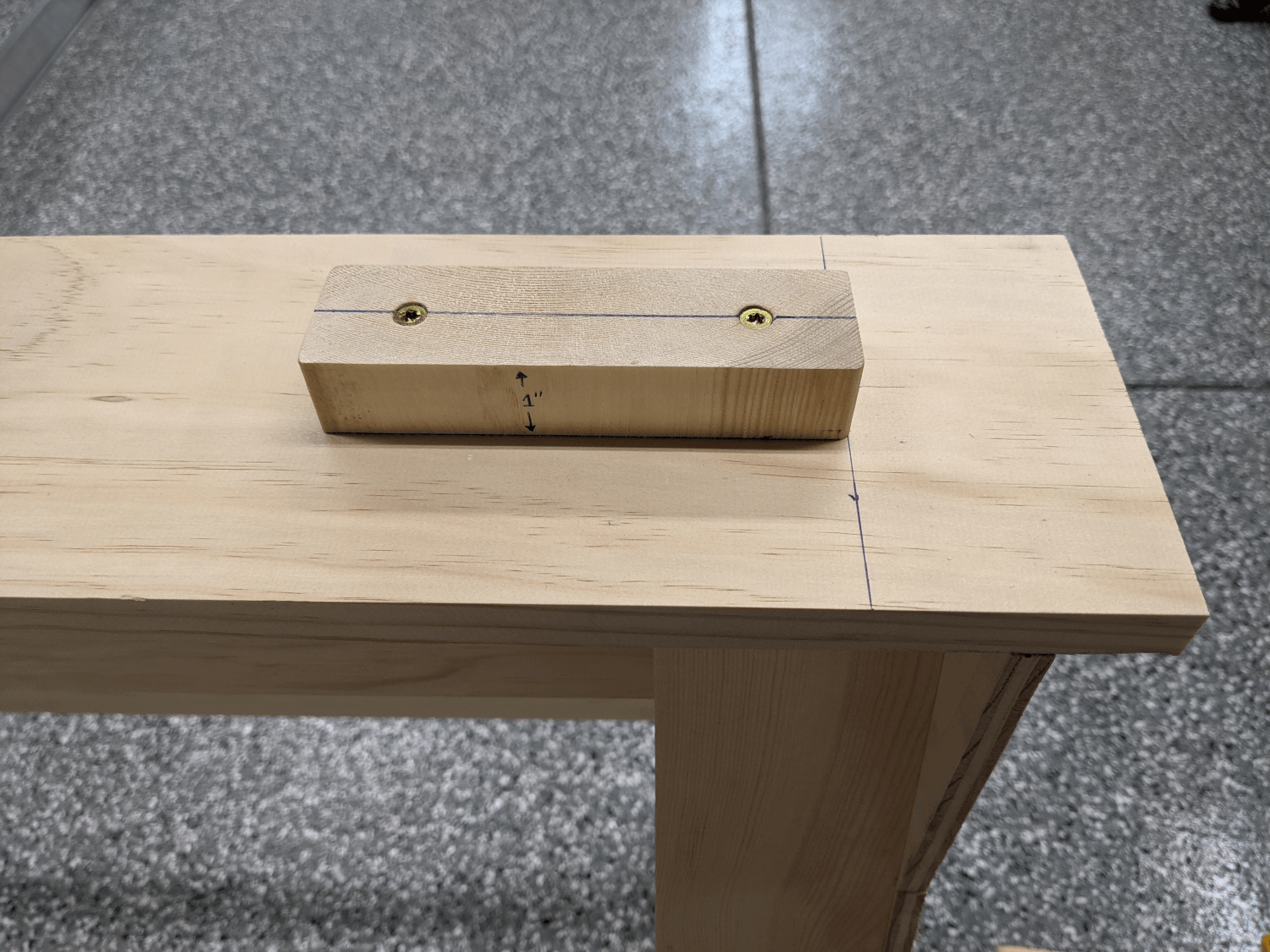
Finally, I positioned and leveled the sawhorses. Martha helped me move the spars off the sawhorses and ensure that both ends were 151” apart. This made them pretty square but we double checked by using the front spar as a straightedge. Then I installed the 1” block on the sawhorse that would hold the outboard edge of the rear spar (as specified in the manual1).
 Block installed on the sawhorse
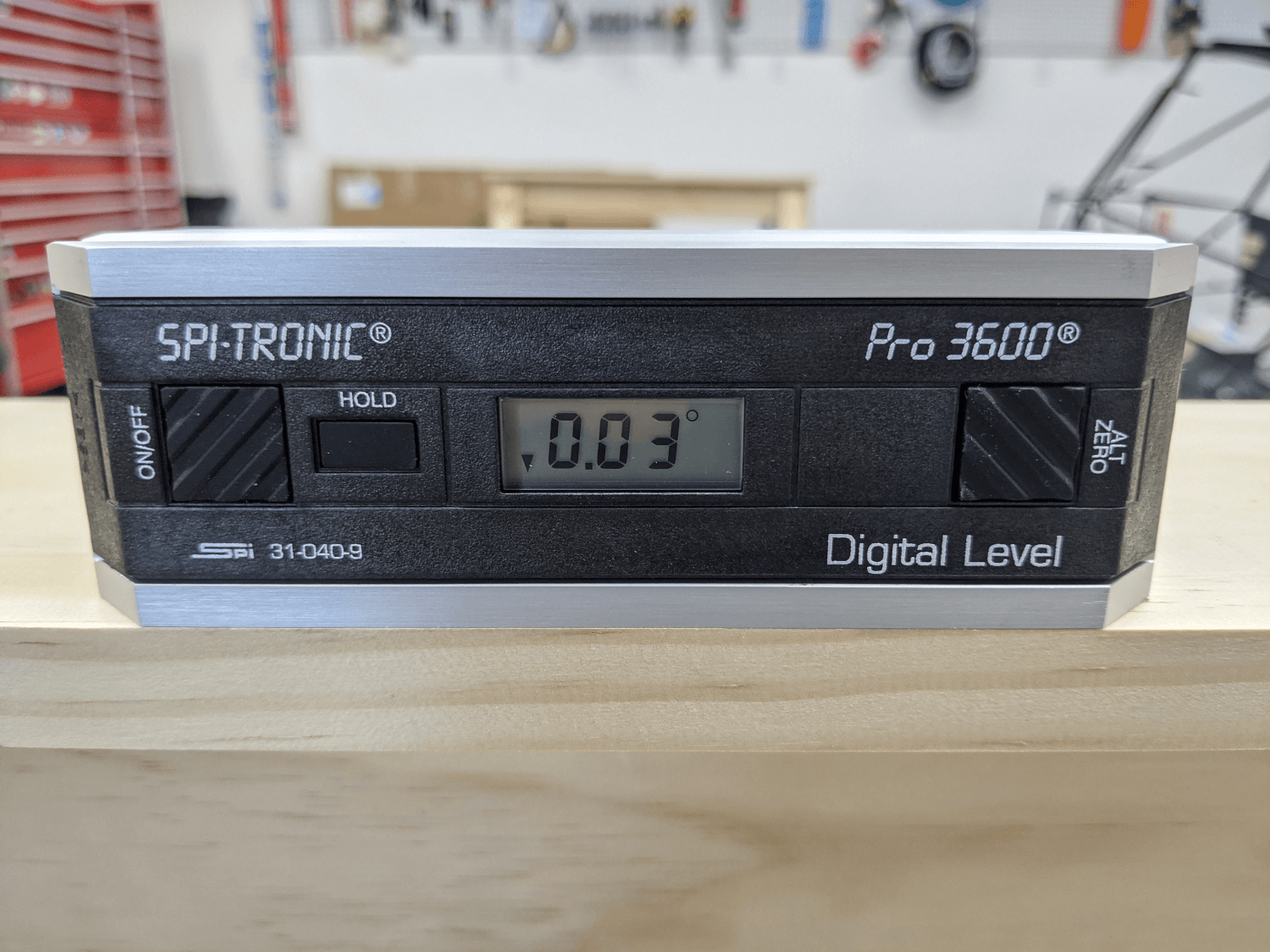
Once the sawhorses were positioned and the block was in place, I calibrated the digital level (SPI-TRONICS PRO 3600) I borrowed from Craig (thanks, Craig!) and leveled the sawhorses side-to-side by installing steel shims under the necessary feet.
 Level sawhorse
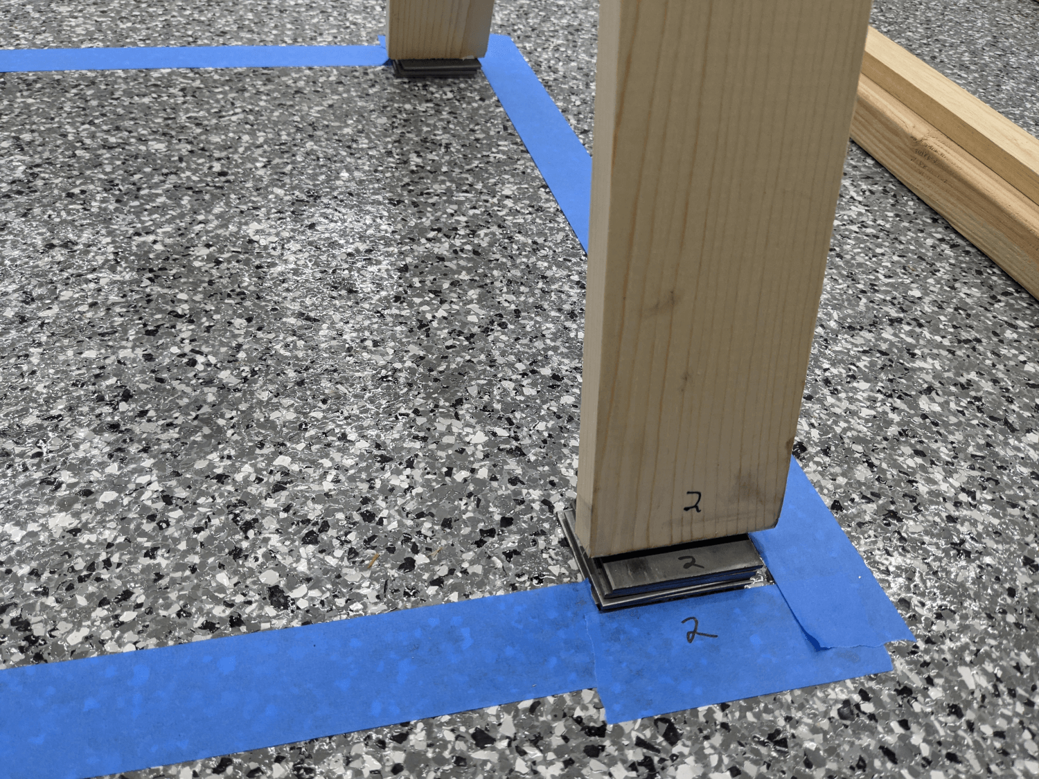
Finally, I placed tape around the feet and marked them so that it was obvious where they were supposed to be. Martha then helped me move the spars back onto the sawhorses.
 Sawhorse foot with shims installed and tape marking position
At this point I am ready to install the drag tubes but unfortunately can’t do that until I receive and install the correct AN6-20A bolt (the bolt head is covered by one of the tubes). Hopefully I will get that early this week.
Wing Manual (Extended Fuel), CCEX-004 Rev. 2.02, Page 27 ↩