My grandfather came in to visit for the weekend and we got to work on the plane together some which was awesome! Since we were still waiting to be able to remove the rivet from the wing we decided to get started on the fuselage assembly a little bit.
We decided to jump ahead to step 1 of section 4 of the fuselage manual1. Section 4 deals with pre-assembly of a number of components and step 1 specifically is the assembly of the rudder/brake pedals. We decided to start here because it wasn’t dependent on anything else (or getting to the fuselage) and would be a sufficiently time-consuming step that it would be nice to get it out of the way (and to have some help).
The diagrams in the manual make it pretty clear how everything is supposed to fit together so figuring out which parts to use and how to assembly everything wasn’t a challenge. The hard part was the fact that the bottom pedals (the pedals are made up of two parts - an upper and a lower section) were too narrow to fit over the bracket that is mounted to the floor. This is especially true since the pedal needs to be able to pivot on this bracket when you push it and you need to fit a washer between the pedal and bracket on each side.
The manual acknowledges this difficulty by saying that “You may need to spread the rudder pedal slightly to allow for the AN960-416L between the pedal and bracket.” This turned out to be quite the understatement since the pedal had to be spread a fair bit to even fit around the bracket, let alone to fit the washers in between. Furthermore, since the pedal was pre-bent and welded it wasn’t very keen on spreading (and there was no way to do so while keeping the sides parallel).
The manual offered no advice about how to spread the pedals so my grandfather and I came up with the idea to use a bolt with a nut on each end going through the holes where we needed to spread the pedal. Then we could turn the nuts to effectively lengthen the section of the bolt on the inside of the pedals and cause them to bend. We thought that the mechanical advantage this would provide would make things easy and that it would give us nice, precise control.
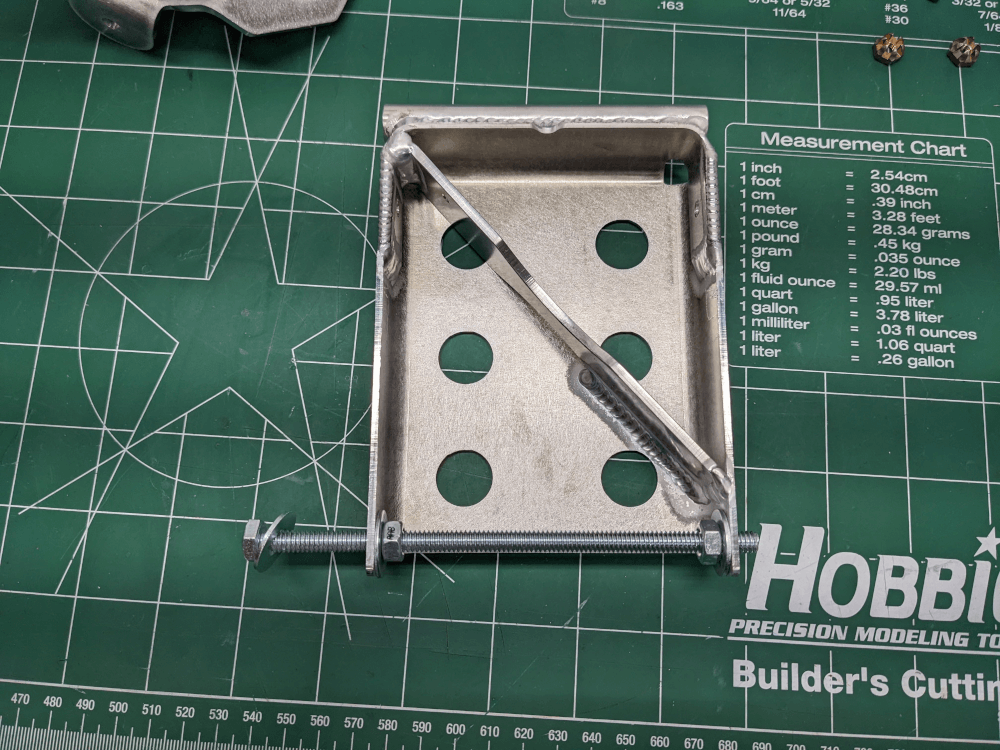 Trying to spread a rudder pedal with a 1/4” bolt
Unfortunately, when we tried this using a 1/4” bolt, the pedal spread while tightening the nuts but returned to its original shape when they were loosened. This obviously didn’t help. We ended up getting the pedals to bend some by over-tightening the nuts so that the metal didn’t quite return to its original position. The problem, however, was that this just caused the material to bend outwards which increased the clearance at the top of the hole but not at the bottom (which was still very tight).
We needed to think about this some more and ended up clamping the pedal to the work bench and using a large Knipex plier wrench (effectively a channel lock) to bend the metal away by hand. This did the trick and we were able to fit everything together. That being said, it was still a tight fit and we had to use an awl through the hole to get the washer between the parts lined up so that we could get the bolt (and its bushing) in place.
Once we got the bottom pedal on the bracket the rest of the parts went together nicely. We had started with the rear pedals so we attached the master cylinder for the brakes to just the top (as instructed) and put on all of the fittings. I had a bit of trouble getting the plastic elbow into the “brake reservoir” (a short piece of plastic tubing) but my grandfather had the fantastic suggestion of holding the tube in a bit of boiling water for a few seconds. This softened it just enough that I was able to slide the pieces together without much difficulty.
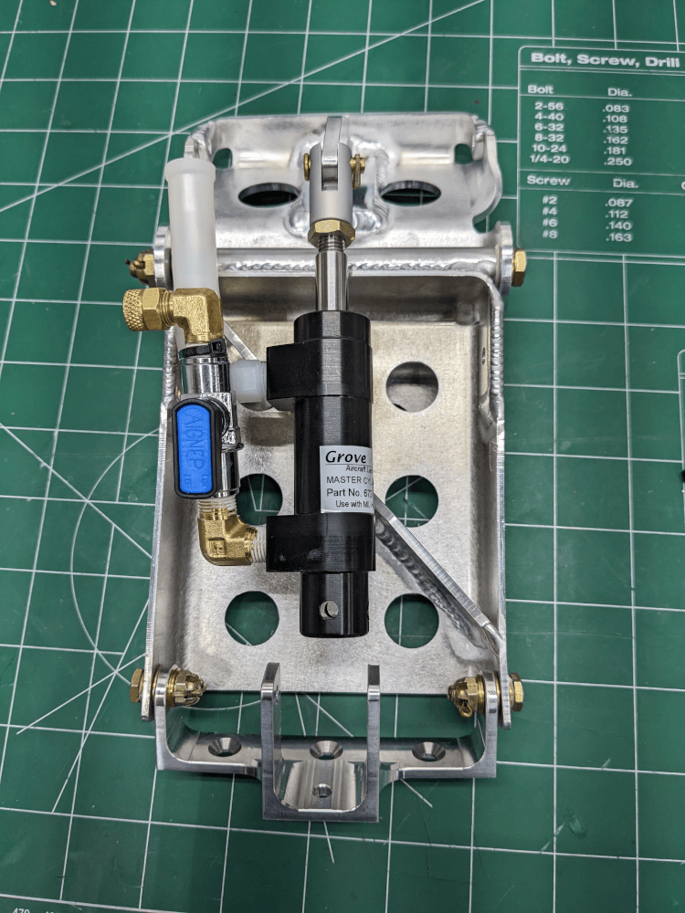 A fully-assembled rear rudder pedal
The next two pedals also went together fine (now that we knew the technique); unfortunately, the last pedal (front right), had a bit of a problem. The tube welded to the top of the bottom pedal section (that holds the bolt to connect the halves) was welded a bit off-center. Neither of us realized until we tried to assemble the two halves. The bolt didn’t want to go through very easily although we were able to tap it through with a mallet. Only once we did that did we realize that the off-center weld caused the top pedal to be off-center enough that it contacted the bottom bracket and wouldn’t move.
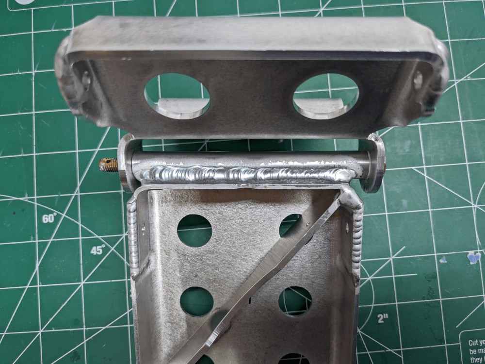 The off-center weld causing the pedal halves to contact and not move
This unfortunately just meant that it was a bad part and that it will need to be replaced by CubCrafters. This is an easy fix although it was a bit of a pain to have three of the four pedals done and not be able to finish the last one.
We did go ahead and completely finish the first three rudder pedals by applying the grip tape as shown in the manual. Unfortunately, even applying it as shown, we were about 8” short of being able to do all of the pedals so I will need a bit more of that from CubCrafters as well.
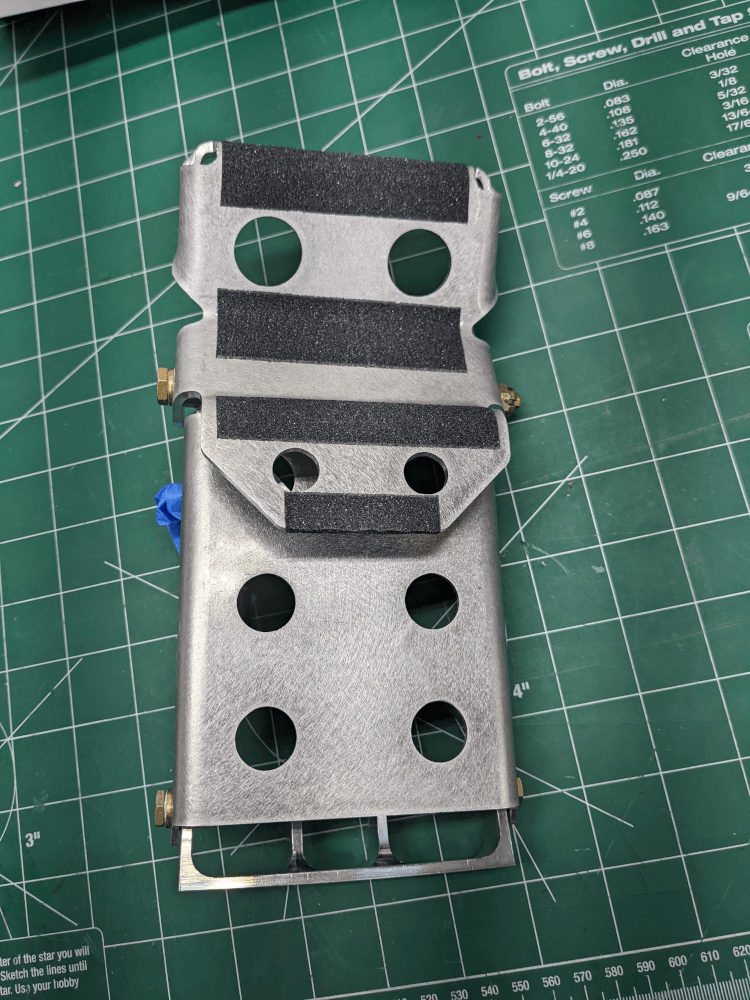 Grip tape applied to a rudder pedal
Finally, before wrapping the completed pedals in bubble wrap and putting them away, I taped over the open fitting ends for the brake master cylinders with masking tape to prevent any dust or debris from getting in there while they are being stored.
Fuselage Manual, CCEX-002 Rev. 2.00, Pages 14-19 ↩