Yesterday, we completed all of the disassembly necessary to get to and remove the rear hinge block on the left wing. So today we could focus on replacing it. Once again, the steps we had identified were:
- Ream the new hinge block (we left this somewhat unspecified).
- Slide the rear hinge block back into place, along with the the compression tube and front fittings.
- Finish installing the bolts in the hinge block and torquing them.
- Install/re-squeeze rivets in the front fittings.
- Re-install the drag wires and set them to the same length as they were before.
- Re-tighten the fuel tank straps.
- Re-apply torque seal.
Step one was the one that we were most unsure about and also the most critical, since getting a good fit on the replacement fittings was the entire reason for doing this. We used modified procedures from section 91 of the manual - the section that initially described the installation procedure for these fittings. The modifications were because we didn’t want to ream all of the holes with the fitting mounted to the spar, since we wanted to reduce the risk of enlarging the holes through the spar web any more than was necessary.
Instead, we attached the fittings together using bolt clecos through the first and last holes, as seen below. We then clamped the assembly snugly to the workbench and reamed the lowest 5/16 inch hole (the one that is directly next to the 1/4 inch hole) using an undersized (.3110”) reamer. We were then able to put a bolt in that hole and snug on a nut (it was a tight fit, which was good). With that done, we removed the cleco from the 1/4 inch hole and reamed that with an undersized (0.2490”) reamer too.
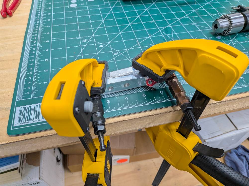 The setup for match reaming the first hole on the bench
At this point, there was one more hole that needed to be reamed that would have a bolt fit through the spar web (the second hole from the top). We debated about whether to do this on the bench too, or to do it on the wing. We ultimately decided to do it on the wing. Our thought process was that, if the holes line up and are smaller than the hole in the spar web, we won’t remove any material from the spar web anyway, so it won’t matter where we do it. However, if there is a bit of an overlap, material would need to be removed from the web no matter what. And if we did that with a single pass we would be removing the smallest amount of material possible.
With that decided, we slipped the hinge blocks back onto the wing along with the compression tube and front fittings. We cleco’d the front fittings in place and used the bolt clecos through the holes we had reamed to hold the hinge blocks in place. We then removed the 1/4 inch cleco and replaced it with a brand new bolt (and the appropriate washer). It was definitely a tight fit so we had to lightly tap the bolt, which was good, and lubricate it with some lithium grease. We also had to use a Knipex pliers wrench to hold the two sides of the fitting together so they didn’t push out while tapping the bolt in. With that one done, we repeated the procedure for the 5/16 inch bolt we had already reamed (including the tapping and holding the halves together).
At this point, we critically went ahead and placed the washer called for by the manual in between the fittings at the top hole and placed the 5/16 inch bolt cleco in there to hold it roughly in place. This would ensure that the positioning for the final hole to ream would be perfect and wouldn’t change later on (like I think it might have when I first installed this fitting). We then put some temporary nuts on the bolts we had already installed and snugged them. At this point, we reamed the top hole through the fitting and the web using the undersized 5/16 inch reamer and then installed a bolt using the same procedure as before (lithium grease, light tapping, holding the halves together with a wrench). We snugged a nut onto that bolt too and, using another washer to press on the washer at the top bolt hole, tapped the washer into place where there was clearance between it and the edge of the hole all around (so it wouldn’t get hit with the reamer). Finally, we reamed this top hole with the undersized reamer and test fit a bolt (it was a tight fit but did slide in with a bit of pressing, without the need for tapping with a mallet).
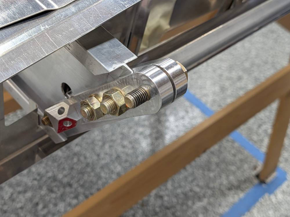 The fitting fully reamed on the spar and ready for torquing
Leaving the top bolt in place (to ensure nothing could move and make the two halves not align there), we removed the nut from one bolt at a time and replaced it with the appropriate lock nut, torquing it in the process. When we were done, we were able to pull out the top bolt, although it had definitely gotten tighter in the process and we had to use a Knipex pliers wrench to grip the head and gently twist back and forth as we pulled. This seemed about as perfect as that could have been. This finished up the re-installation of the aft hinge block! Critically, the fit was very good and much tighter than it was before. This meant that it was good-to-go and that the disassembly and replacement had been a success! Now, all we needed to do was to reassemble everything else.
We started doing that by re-squeezing the rivets in the front fittings per section 6 of the manual2. This was pretty straightforward, although we did have to remind ourselves how to get the squeezer in there for a few of them. The nice thing about this step is that you can take it slowly and measure the shop head of the rivet as you go, until it has been sufficiently (but not overly) squeezed. The pitot and static lines were in the way a bit on the bottom outboard rivet, but not as badly as we had feared actually. Craig was able to help hold them out of the way and we got the rivet done without issue.
From there, re-tightening the drag wires and fuel tank straps was just like the end of the fuel tank installation step (section 58 of the manual3) and was pretty straightforward. It did involve a bit of back and forth to get the drag wire lengths right though. I’ll also mention that we did not yet re-apply the red Loctite to the jam nuts and will probably do that at a later time. I also need to get some new friction tape to apply to one of the chafe protection tubes for the drag wires through the fuel tank (the one on the large wire - the tape just keeps it from sliding back and forth). These are both pretty minor things though. I did re-apply torque seal to all of the nuts/bolts though.
Finally, we realized there was really only one step left on this wing, section 564 - trimming the tip bow. All we had to do for this was trim the rear section of the tip bow to be flush with the machined tail rib. Craig had recommended this 1 inch rotary tool sanding kit before, and I had already purchased it for this task. I taped over the metal and the top of the tip bow and, using one of the medium grit sandpapers (180 or 240), shaved away the tip bow until it was flush. I then removed and reapplied the tape before doing the same thing to the top edge. We made sure to wear breathing and protection while doing this.
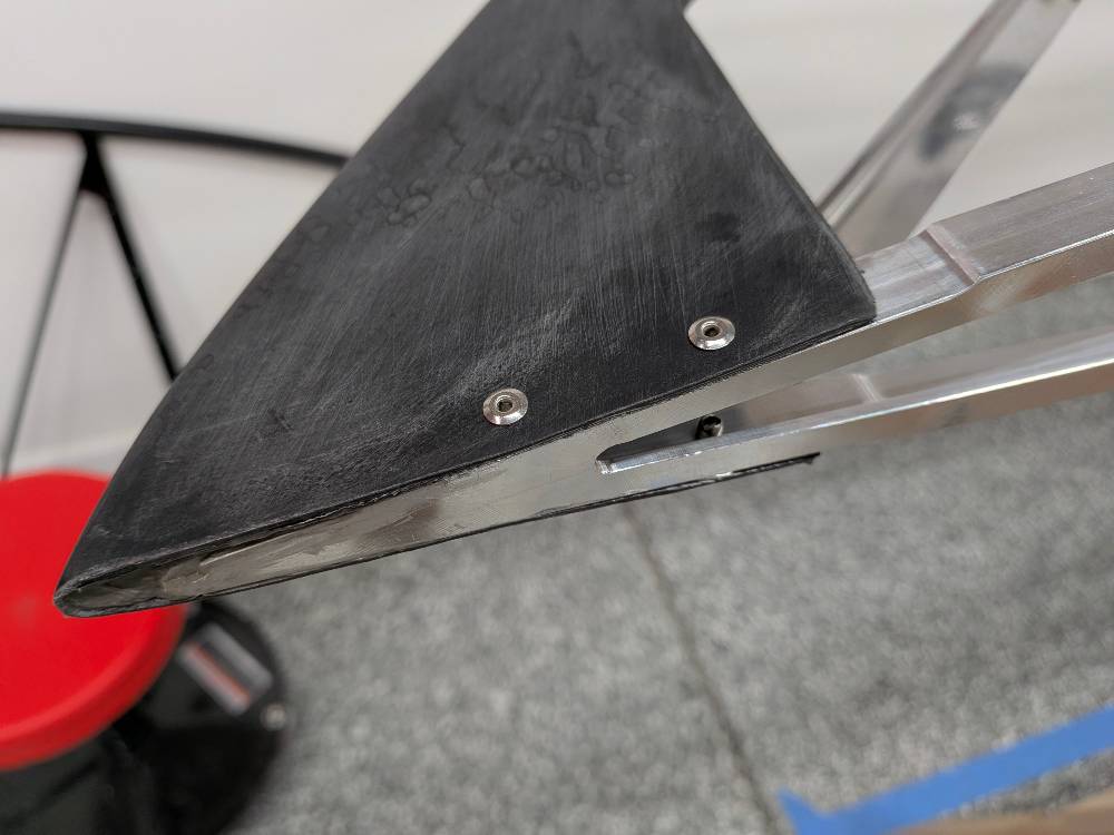 The left wing tip bow trimmed to be flush with the machined rib
I believe section 605 (false spar aileron cable relief) may no longer need to be done so this just about finishes the left wing build! I’ll put the friction tape (mentioned above) on something this week and then I do need to go back through the manual and to check all of the inspection points. Especially since it’s been so long since I worked on this. The last things I’ll have to do are the foam spacer blocks (section 626) and the red Loctite (as mentioned above). But both of those things are relatively trivial and can be done before covering time. I’ll have to pretty thoroughly clean the wing at that point anyway, I’m sure.
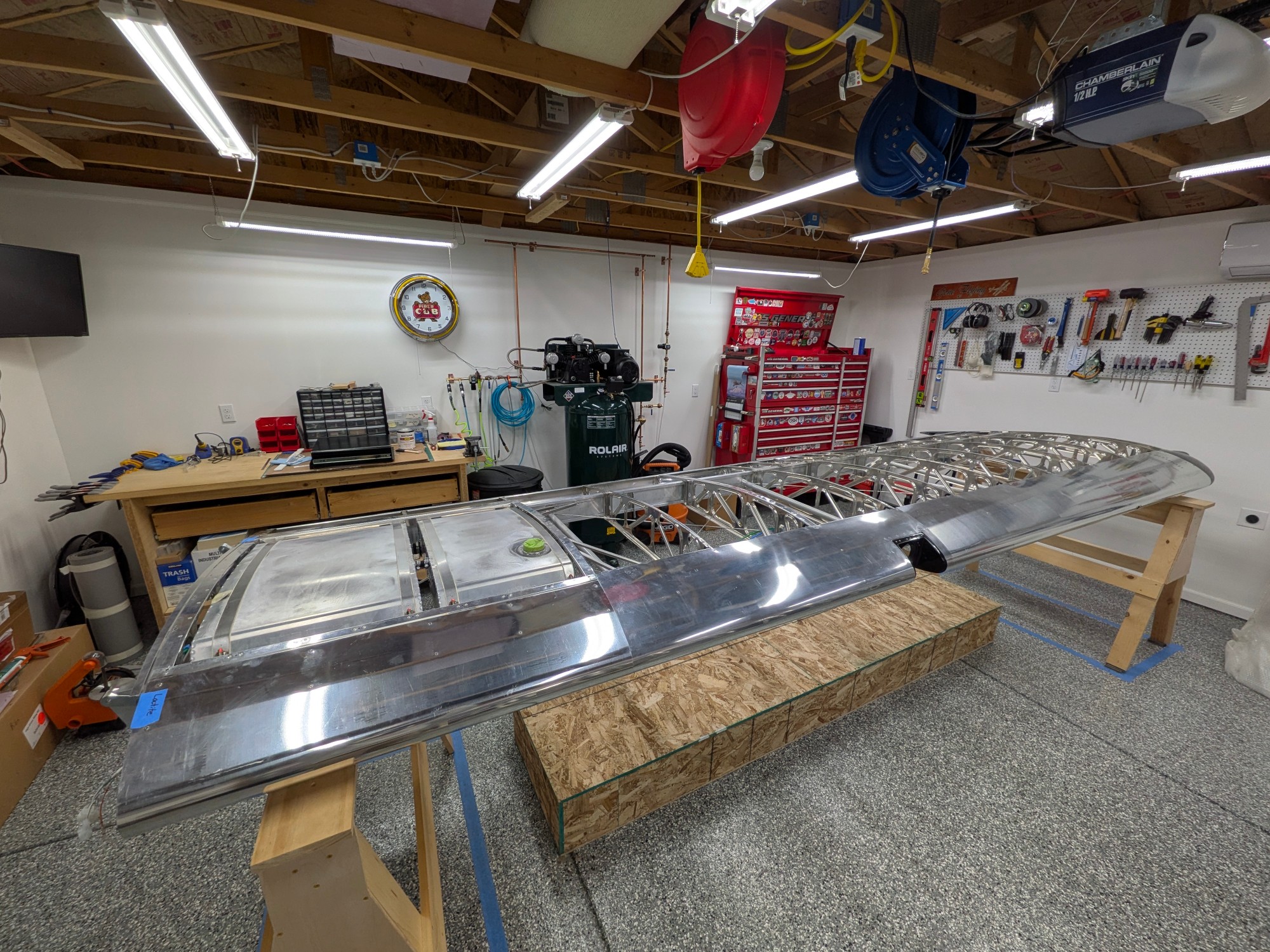 The finished left wing
Wing Manual (EX-2/EX-3) CK-KM301 Rev B, Section 9 ↩
Wing Manual (EX-2/EX-3) CK-KM301 Rev B, Section 6 ↩
Wing Manual (EX-2/EX-3) CK-KM301 Rev B, Section 58 ↩
Wing Manual (EX-2/EX-3) CK-KM301 Rev B, Section 56 ↩
Wing Manual (EX-2/EX-3) CK-KM301 Rev B, Section 60 ↩
Wing Manual (EX-2/EX-3) CK-KM301 Rev B, Section 62 ↩