The plan for today was for Craig to come over with the jig he made to try to help remove the problematic rivet from the front pulley bracket. My grandfather and I had a bit of time while we were waiting for him so we decided to do a bit more work on the fuselage.
Fuselage Work
We started by completing the next component pre-assembly step by assembling the electric trim jackscrew assembly per section 4 step 2 of the fuselage manual1. This was a really easy step that just took a minute or two since there were only two bolts and everything went together really nicely. Once this was done I put it back in one of the bags the parts came in and put it back in storage for the time being.
 The completed jackscrew assembly
We also completed section 1 of the manual2 by inspecting the fuselage for any damage. I had already noticed a few places where the powder coat had work off and painted those areas with some enamel metal paint but we did find a couple more that we marked with masking tape. I’ll need to go back and touch these up before calling section 1 done.
After that, we removed the powder coat from the rear of the top-left engine mount per the instructions in section 23. This is done to provide a ground connection between the engine mount and the fuselage frame. The picture in the manual shows this being done with a die grinder but I just used some 150 grit sandpaper and it only took a couple of minutes. This completed section 2.
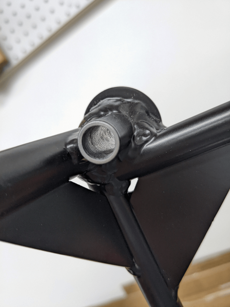 The engine mount with the powder coat removed
Finally, before Craig arrived, we completed section 3 of the fuselage manual4 by inspecting the boot cowl spacers for damage. Everything looked good so there was nothing to do here.
Removing and Replacing the Rivet
Craig then arrived with the jig he made for cutting the back of the rivet. The gap between the spar web and the spar bulb in the front spar is 0.19” and he was able to find some 0.19” aluminum stock from McMaster that he welded to a sheet of aluminum. He put a drill bushing sized to exactly fit the shaft of a cutoff disk in that sheet. This bushing was placed far enough down that the jig would contact the spar before the cutoff disk would if we pushed it too far up. Finally, he bolted on a thin aluminum sheet to go between the cutoff disk and the bulb to provide extra protection.
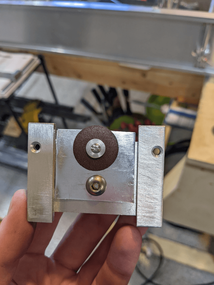 The side of the jig that faced the spar web
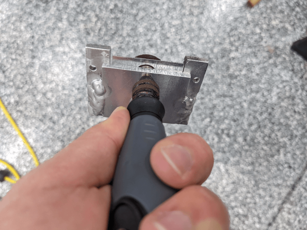 The cutting jig attached to the Dremel tool
I attached the jig to the flex shaft on my Dremel tool to give more control and so that the check could go all the way up against the jig and prevent the cutoff disk from extending too far. We then made sure everything lined up okay and, very carefully, began cutting the rivet.
I held the jig and pushed it up into the rivet, Craig watched to make sure we weren’t getting close to anything important, and my grandfather controlled the Dremel tool’s power. We cut a little bit at a time until we had a cut through most of the exposed rivet shaft.
Unfortunately, since the rivet shaft was wider than the cutoff disk and part of the rivet shaft was above the bulb (why we were having problems to begin with), we couldn’t cut all of it off. Instead, we put a cut through the middle of the shaft. We thought this would at least weaken it and make it bend more easily if we tried the method of shielding the bulb with the aluminum sheet and tapping the rivet stem out.
This is what we ended up doing - I tapped the rivet stem out using a pin punch and a small mallet, my grandfather held the spar shield in place, and Craig watched the progress of the stem coming out. It took a few taps but the rivet stem did bend and came out!
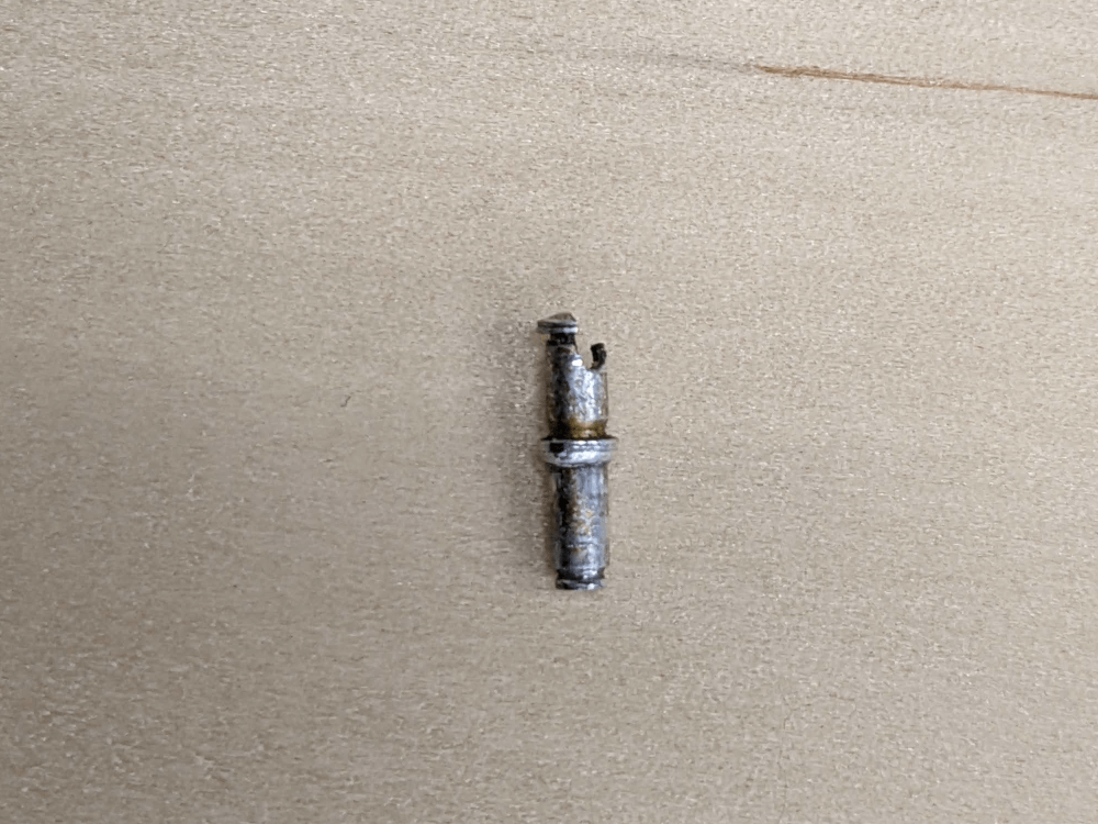 The rivet stem after being removed
Once the rivet stem was out my grandfather was able to use a 1/8” punch to drive the aluminum part of the rivet out the back - the rivet was finally removed! Fortunately the hole still looked good and was ready for a new rivet to be installed.
We tried the rivet setting technique again where I pulled slightly with the hand puller, Craig helped me push the rivet down, and then we repeated the process until the rivet head was flat on the work piece. I then pulled the rivet the rest of the way using the pneumatic puller. Fortunately, this time the rivet pulled correctly and the bracket was fully riveted on!
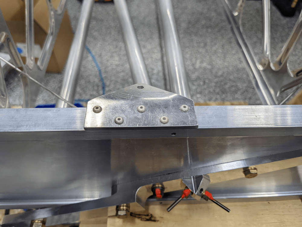 The finished bracket fully installed
I still need to go back and buff the scrape on the bulb a bit before I consider this section5 done but it’s pretty much there and we’re about ready to move on! We decided to end on a high note by stopping here but I’ll start the next build session by buffing out the scrape before moving on to section 19. I’m really glad to be unblocked on this and to be able to try to make some consistent progress again!