I have to start this build log entry with a bit of a story. One of the first things you do, per the manual, when working on the wing is reaming and installing the lift strut and hinge block fittings. This is certainly unlike anything I had done before building the plane and was not something I was familiar with at all. When I did it, I followed the manual’s procedure; however, there was an issue with the rear fitting. The top set of holes (that attach to the fuselage) don’t have any of the spar web between the two halves of the fitting. Because of that, you’re supposed to put a washer in between them (to act as a spacer). I initially reamed the holes without the washer in place and tried to install it later. When I did, I realized it wouldn’t slip in and that I had to loosen the bolts to get it to fit. When I did, the bolts no longer fit in the top two fitting holes. So I re-reamed them so that the bolts would fit. I assume this is because the angle between the fittings changed ever so slightly with the washer in place.
Because the hole was re-reamed at a slightly different angle, it was no longer perfectly round and now had a bit of extra space. Putting a bolt through it, there wasn’t a lot of wiggle, but there was certainly a bit. I emailed Cub Crafters to check to see if this was okay, and made a post in the builder’s group to check there. Both sources told me they thought it was fine. That being said, I continued to be somewhat uncomfortable with this. As the left wing was approaching completion, I decided to check with Cub Crafters one more time to see if they still thought this was okay. They said that they couldn’t say conclusively one way or another without doing an engineering analysis on it but that they thought it would be better if it were tighter. They also said that they thought the best course of action would be to replace the fitting. Unfortunately, the drag wire in the first wing bay also goes through this fitting, as does the first compression tube. This meant that there would be a non-trivial amount of disassembly to get to the fitting. This was made even more challenging since I had already put the red Loctite on the drag wires, which would make them harder to remove. This was all pretty discouraging and, since my wedding was coming up, I put the project down for a while, although I did order the replacement parts I thought I would need.
Fast forward to today, I had never picked the project back up because of the aforementioned discouraged feeling about it. Fortunately for me, Craig texted me telling me he was free and asking if I wanted to try to get this part done. I knew I was going to have to be dragged back into the project and, even though I didn’t really feel like doing it, I thought this would be the best opportunity I would get. So we took some time to look at the plane and remember what we had to do last weekend. Then, we started doing the actual disassembly today.
The first thing we did was come up with a plan. Specifically, we listed the steps we needed to complete and the order in which we needed to complete them. This was influenced by the fuel tank removal service document that Pete from Cub Crafters shared with me. A lot of this didn’t apply, but the parts about removing the drag wires was relevant. For disassembly, the process we came up with was the following:
- Measure the amount the drag wires were sticking out, so we could return them to that position (this is the same process that is used when removing the drag wires to install the fuel tanks).
- Loosen the fuel tank straps so that they wouldn’t be pulling on the spars without the support of the drag wires and compression tube.
- Remove the nuts on the inboard end of the drag wires (this is one of the parts we were nervous about, because of the Loctite).
- Drill out the rivets holding on the front drag wire/compression tube fitting.
- Remove the nuts on the rear hinge block.
- Remove the bolts from the rear hinge block and slide the hinge block, compression tube, and front fitting out as a single assembly.
The procedure we came up with for reassembly/replacing the hinge block was largely the reverse:
- Ream the new hinge block (we left this somewhat unspecified).
- Slide the rear hinge block back into place, along with the the compression tube and front fittings.
- Finish installing the bolts in the hinge block and torquing them.
- Install/re-squeeze rivets in the front fittings.
- Re-install the drag wires and set them to the same length as they were before.
- Re-tighten the fuel tank straps.
- Re-apply torque seal.
Steps 1 and 2 for removal were pretty straightforward. We used a crows foot to hold the head of the fuel tank bolts and then a socket to loosen the nut. We didn’t fully remove it though since it required a jig to get the nut started and it didn’t seem necessary to fully remove them as the straps seemed loose enough with the nuts just loosened. Measuring the drag wires was also relatively straightforward with the help of digital calipers.
Step 3 was one were worried about because of the Loctite. That being said, we had tested this with a separate bolt on the bench and we were able to break through the Loctite relatively easily just using a wrench, so that gave us hope. It turns out, we were able to do the same thing here, without having to use excessive force or heat. The hardest part was figuring out how to keep the drag wire from spinning. We ended up doing that by using several more nuts, jammed together, on the part of the wire that was still sticking out. We had to use 3 nuts on the thicker wire and re-tighten them a few times, but this worked pretty well. Definitely better than trying to grip the wire itself with pliers or something. In fact, we were initially thinking we might have to replace the drag wires, but the threads all seemed fine after we were done removing the nuts and nothing seemed like we would have damaged the wires, so we were able to leave them in place and re-use them. This greatly simplified the process and kept us from having to re-trammel the wing.
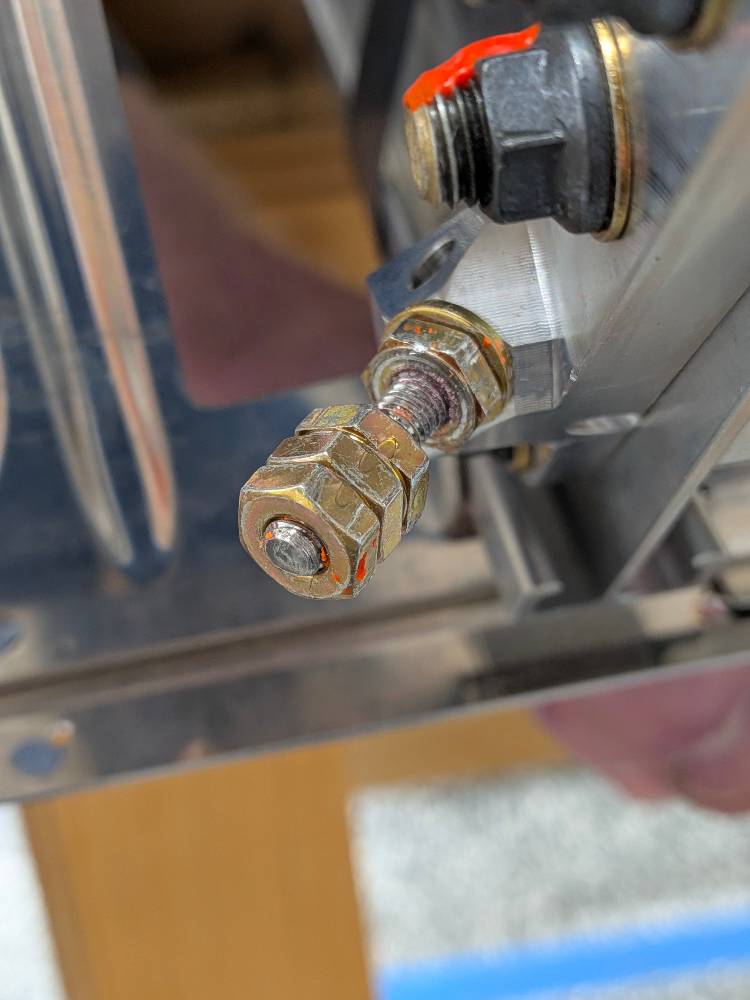 Using additional jam nuts to provide something to grip the drag wire by
Drilling out the rivets in the front fitting was also pretty straightforward. Using a rivet removal tool, this was pretty easy and not incredibly stressful. The hardest part was working around the pitot and static lines, that had been installed, but that was only an issue on one of the rivets and didn’t actually cause as many problems as we thought it would. We used an automatic center punch to punch the rivets out of the holes.
Removing the nuts and bolts was also simple, and then the fittings and tubes slid out just as easily as we had hoped. Overall, this all went way more smoothly than we thought it would, and we really didn’t have to do anything that felt uncomfortable or iffy. It was really great getting it to this point!
 All the fittings removed and ready for re-installation