I started today working on my own a for a bit in order to get the left wing ready for the fuel tank installation. I had already retrieved the tank from the shed, unwrapped it, and installed the tubing for the drag wires but there was still a bit left to do. For starters, I removed the jam nut from the inboard end of each drag wire in the fuel tank bay and measured the amount of wire that stuck out past the remaining nut using a set of digital calipers. I measured this value for each wire a number of times in order to ensure it was repeatable and wrote down the common values for each. After that, I cut the safety wire that was temporarily holding the two halves of the fuel tank straps together and opened them all up. There were a few small aluminum shavings in the felt on the straps so I cleaned them with the air blow gun.
At this point, I was still waiting for Craig to come help me with the fuel tank installation so I drilled all of the additional fabric rivet holes in the right wing per section 631. This was actually much easier with it in the stand than it was on the left wing since I didn’t have to crawl under it.
At this point, Craig arrived and, after he gave me a bit of a rundown on the wingtip install and answered a few other questions that I had, we got started by drilling the hole for and installing the last rivet on the spar side of the leading edge skin (just inboard of the leading edge pulley bracket). We had initially decided to come back to this one when we were drilling these rivet holes since we needed to use the small jig that Craig made but failed to see it and therefore missed it. With it now installed, section 502 was officially done on both wings!
From there, we moved on to the fuel tank installation. We took the final nuts off both drag wires and retracted the thicker drag wire into the leading edge skin as far as it would go. We then slid the thick black tube over this drag wire but left just a bit of the tube hanging off over the end so that we would be pushing plastic (instead of steel) up against the fuel tank when sliding it through. We also carefully removed the thin drag wire entirely and took out the clecos holding the rib #3 braces to the spar. At this point, we got help from Martha (so we would have 3 people) and placed the fuel tank into position. In order to do this, I lifted it and began feeding it down the thick drag wire. When the drag wire got to the middle, Craig ensured that it passed under the plastic tubing for the thin drag wire (as specified in the manual). The whole time we were doing this, Martha made sure that the short sections of the top fuel tank straps were sticking up and not getting trapped under the fuel tank. Finally, when the tank was almost all the way in, Craig flexed the #3 rib outboard just enough to let the tank clear and drop into place.
At this point, we put two sand bags on top of the tank and tried to position it so that it followed the curve of the top of the wing and was approximately centered side-to-side. This took a bit of trial and error (had to remove one of the straps after initially installing the bolt) but we eventually got there. One of the keys for us were that we couldn’t move the tank after even the first strap was in place so we needed to position it correctly ahead of time. We also had to shift the tank forward some in order to get it to follow the curve of the wing. Another key that made it easier to check was laying a long (48”) ruler across the tops of ribs 1 and 3 so that we could make sure that the eventual tank cover would clear the tank itself and the straps.
With the tank positioned, we started installing the bolts into the straps. Fortunately, Craig welded together a device that lets us pull the straps together with the bolt in place and install the nut without having to mess with channellocks or anything like that to try to force it. There’s a picture of it below but in essence the two bolts on the side were loosened all the way, the washer was inserted in the top, the bolt was inserted through the two tank strap halves, the jig was placed under/behind the bolt head, and then the two side bolts of the jig were tightened until enough of the bolt was sticking up past the washer to allow the nut to be started. The jig also kept the bolt head from turning which was a huge help and made it much easier to install the nut. I should also mention that, in order to get the bolt to line up and pass through the washer as everything was being tightened, a 0.3” thick piece of wood was inserted under the bolt before the jig was tightened too much and removed after the nut was started. This whole setup worked great and the only thing I would do differently next time is just tighten the nuts appropriately (1-3 threads showing) while the jig was still on there.
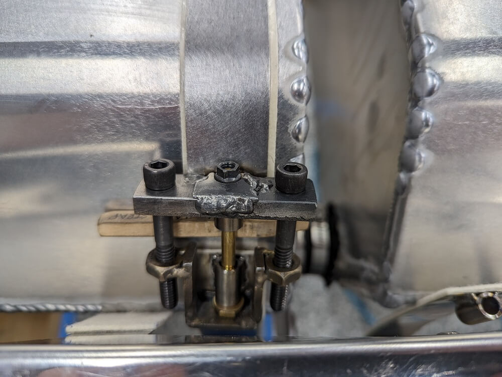 Using the tank strap jig to install a tank strap on the left wing
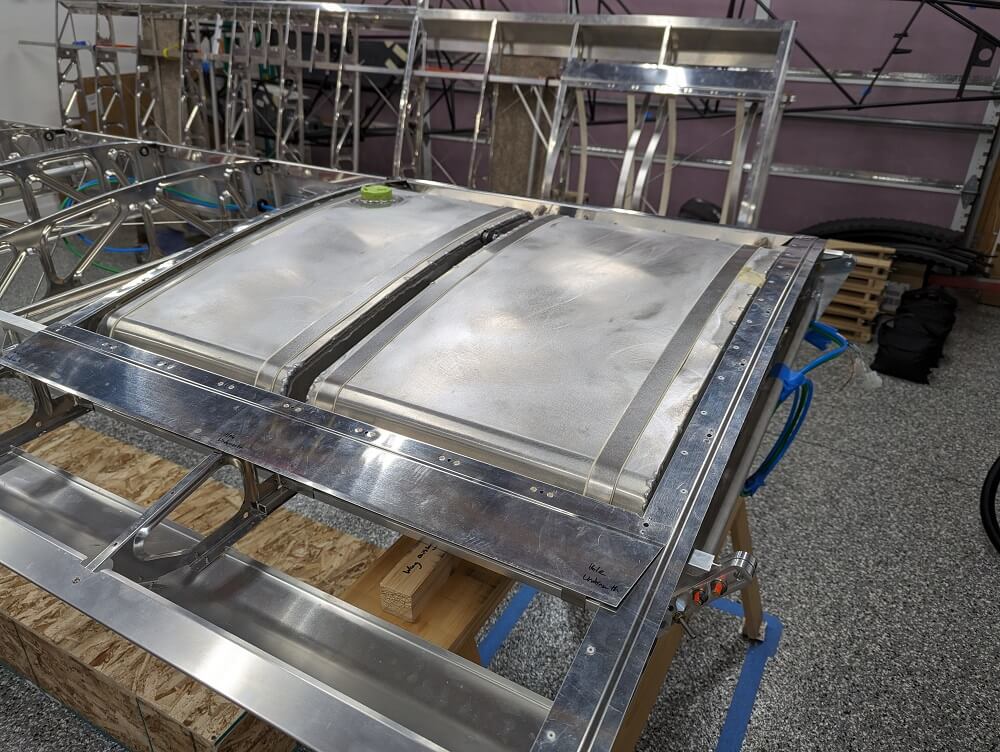 The fuel tank fully installed
After all of the fuel tank straps were installed, we moved on to the outboard center rib (#13). Craig helped me verify that it was in the correct spot and then we drilled all of the holes and installed the rivets, completing section 523. There are several details worth noting here too, however. The first is that when the manual specifies that the rib is centered vertically on the spar, it works out much better if the rib itself, and not the tab that sits against the spar, is what is centered. This had taken me a bit of trial and error to get right but once I did I could see that the rib matched the curvature of the #12 rib and it seemed to make a lot of sense.
It is also noteworthy that the installation of this rib requires drilling into the spar without the use of a pilot hole or drilling jig (since the rib is in the way). Based on Craig’s advice, I solved this by using a deep hole marker (such as this) placed through the #40 hole on the drilling jig to draw a line down the center of the spar cap. This gave me a line that would put the hole in a safe position as long as I drilled the middle of it. Then, with the rib clamped in place, I extended the line onto the rib flange and measured 1/4” from the edge (centered on the extended line) for my drilling position. Each hole was punched first with an automatic center punch to keep the drill bit from walking and then drilled with a 12” #30 bit. It is critical that the leading edge spar is drilled first so that the rib can be bent outboard (somewhat significantly) to allow a straighter approach to the top front hole. It is also critical that the front rivets are pulled first (per the manual) for this same reason.
Finally, the last important note for the outboard rib installation is about clamping. It isn’t possible to clamp the area of the rib that is being drilled since there isn’t enough space. Instead, a piece of wood can be placed across the back of the spar with a clamp between the rib flange (in the middle, not where it overlaps the spar) and the wood to hold it in place. Furthermore, a large clamp can be placed on the outboard side of the rib, up against it, in order to prevent the rib from being pushed sideways while drilling. It’s pretty tight so the drilling ergonomics aren’t great but it’s doable from the top side (using a second hand to help stabilize the long bit).