Today I completed the installation of the machined tail ribs on the left wing. These ribs provide 2 of the 3 mounting points for the ailerons (the ends of the ailerons are mounted to them - a center mounting point is installed later) and the outboard mounting point for the flap. This was a step that I was somewhat apprehensive about since each machined tail rib is held on with 2 AN3 bolts and 2 CherryMAX rivets. The CherryMAX rivets are installed extremely close to a corner in the machined tail ribs which makes it impossible to use a normal/unmodified rivet puller to reach them. Instead, you are supposed to grind down a puller until it is able to fit on the rivet straight and can therefore pull it correctly. There are many posts on the CubCrafters forums and in builders groups asking about this step because even with the help of a ground down puller and often a pulling wedge (to direct the rivet stem out at a bit of an angle and therefore make it easier to pull) many people have had problems and have had to drill these rivets out. Removing CherryMAX rivets is difficult under normal circumstances but these locations make it even harder since you can’t get to them straight with a normal drill or a punch because of their position. A final wrinkle that adds to the complexity of these rivets is that they are too deep to be inserted into the holes fully before you start pulling them so there is a bit of a gap between the factory head and the part. This means that the last bit of rivet insertion into the hole is done while pulling.
Because of the difficulty of pulling these rivets correctly, the difficulty of drilling them out, and the critical nature of the area in which they are installed (the spar cap), Craig and I decided to go in together on the correct tool for the job. We purchased a used CherryMAX G747 rivet puller and a practically new CherryMAX H781A-456 offset pulling head on Ebay. The puller pulls with over 2000 lbs. of force and came with a H701B-456 straight pulling head as well that we can use later on other CherryMAX rivets. Unlike the other pneumatic pullers we have for this project, the G747 pulls much more slowly (over the course of about a second) and seems to set the CherryMAX rivets perfectly. The slower pull also makes the tool much more controllable and makes the rivet stem breaking much less violent. After using the puller for this step I think it was by far the best tool purchase we have made to date for this build, even though it was somewhat expensive.
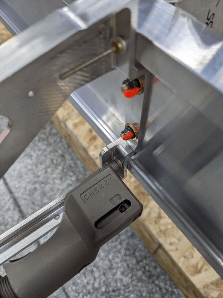 The offset puller on one of the machined tail ribs showing the difficult location and how easy it makes it
Another specialized tool that we needed for this step was a 1/4”, 1/4” drive, crowsfoot wrench. We needed this because the machined tail ribs are angled down in such a way that we could not reach the top bolts with a normal socket. This isn’t a problem for getting the bolts snug since we could use a normal 1/4” open-ended wrench but did present an issue when it came to torquing the bolts. The crowsfoot works with a torque wrench without any problems (as long as you adjust the torque value for the additional lever arm) and easily fit where we needed it to.
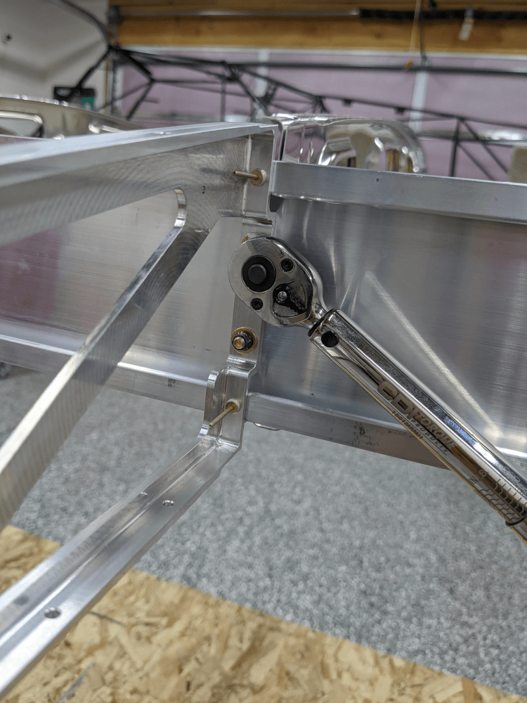 Using the crowsfoot to torque a tough to reach bolt
Equipped with the proper tools, I installed the bolts for the inboard machined tail rib with the rivets set in place to keep the alignment correct. This went on easily and the rivets were still able to removed and reinserted once I was done. I tried this same procedure for the outboard tail rib but there was just enough play in the holes that the alignment was slightly off by the time the bolts were torqued. Even though the rivets were still in place, they were binding on the sides of the holes and could not be removed or moved at all.
Craig later came over to help with the riveting portion since this was a critical step and new to us so we wanted to make sure we were getting it right. The rivets for the inboard tail rib pulled easily on the first try but we wanted to work on the outboard tail rib a bit more before setting the rivets there. We loosened the bolts just enough to get some play and prevent the rivets from binding. At this point, the bolts were still held fully inserted on each side (so they couldn’t get out of alignment and there were no gaps) but we were able to insert and remove the rivets freely. We then pulled both of these rivets (starting with the top one since it was the most difficult to reach, even with the offset puller) which set well on the first try (did I mention how great the puller is?). After that, we replaced and re-torqued both lock nuts, one at a time.
 Fully installed machined tail rib
Both machined tail ribs on the left wing are now successfully installed and section 121 of the manual is now complete. Section 13 involves trimming the nose ribs to prepare them for installation and section 15 instructs the builder to install the inboard and outboard nose ribs (lined up with ribs 1 and 12). The purpose for this is to hold a string line (that is used for trammeling) up off the surface of the spar. Dave Embry points out in his build tips that this is unnecessary and that small blocks of wood can be used instead. This has the advantage of allowing me to install all of the nose ribs at once and to avoid having these two nose ribs installed and in a position where they could get bumped/damaged while trammeling. This makes a lot of sense to me and seems to be a common/supported practice. Because of that, I’m going to come back to sections 13 and 14 when it is time to install the nose ribs and instead proceed directly to section 15 - trammeling the wing.
Wing Manual (Extended Fuel), CCEX-004 Rev. 2.02, Pages 77-78 ↩