Today was another long day of working on leading edge skins - this time on the final skin in the fuel tank bay. The complication of this skin, besides the sawhorse getting in the way and making things challenging, is that the window latch doubler must be installed before the skin. This is a piece of sheet metal installed between the first intermediate rib and rib #2. The manual gives some guidance on its location but doesn’t make it obvious where it should go and I really didn’t want to end up with a fit problem. Because of that, I tool several steps to make sure it was in the right position before drilling.
First, I put the clamps on the skin and tightened them so I could mark the back side of the skin on the bottom of the ribs. This would provide the most rearward position the doubler could go on. After that, I removed the clamps and marked the hole positions on the doubler, including the location of the most rearward hole in each rib that is shared with the normal bottom hole position of the skin. With that done, I clamped the doubler into place with this most rearward line 3.2” from the spar (where the most rearward hole in the skin is supposed to go). This came out pretty well aligned with the mark I had made earlier for the rear of the skin but I test the fit with the clamps on more time and cheated ever so slightly forward with the doubler (I really didn’t want it to be too far aft). Finally, after triple checking the position and making sure that it was square (the measurement to the spar was the same on both sides), I marked the rib center line on the front of one side, center punched, and drilled. With that done, I inserted a cleco and did the front on the other side. Since these holes don’t go through the skin and are riveted first, I removed the part, deburred, and then installed it with rivets.
At this point, I was able to install the skin mostly normally although I had to be careful to get the back lip of the skin around the doubler as I tightened. This had to wait for the clamps to be tightened a little bit (to get it in about the right spot and hold it there) but I didn’t want to tighten too much before I did this because it would smash the lip into the doubler.
The rest of this skin went pretty smoothly except for the final hole into the bottom of rib #1. Because of the capstrip, it’s hard to tell where the nose rib actually is. Next time I will mark that on the capstrip before putting the skin on (like on the top) but in this case I had to try to measure over from the side. It turns out, I got a bit too close to the side of the nose rib and, because I had to drill in an awkward position with a long bit because of the clamps, my bit drifted over even a bit further. The edge distance from the side of the capstrip was fine so I think this would have likely been okay; however, I wasn’t happy with the distance on the rib so, after consulting with Craig, I adjusted my measurement and drilled one more hole 1” farther forward and installed a second rivet. At this point, section 49 of the manual1 (installing the leading edge skins) was done and I was able to remove the last section of PVC (through the window, with Martha’s help).
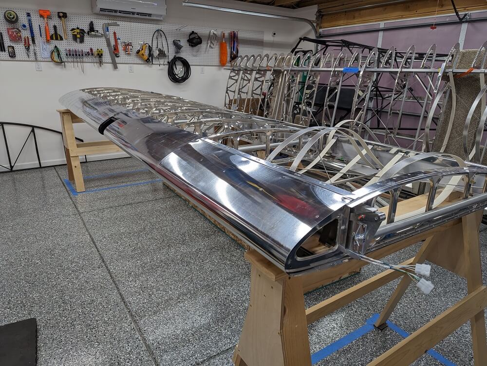 The finished leading edge skins
With the skins installed, the next step was finalizing the spar side by match drilling holes and pulling rivets. The manual2 gave some guidelines but not precise locations so I spent a while measuring and marking where I wanted these. The drilling jig should be used as to not hit the spar bulb so there were a few places I adjusted slightly to make this easier (still keeping to their parameters). That said, there are still a couple spots where a smaller/shallow jig must be used. Fortunately for me, Craig had already made on of these. The one other place to watch out for is in the fuel tank bay near rib #2. There is already a hole here for the #2 rib that was not installed on top and it’s important to not accidentally partially hit this and make it an enlarged, ugly hole.
I wanted to wait for Craig’s help to actually drill these holes so I decided to do a bit of section 513, installing the landing light housing, before calling it a night. I centered it and taped it in place, as depicted in the manual, before marking the line of rivets across the top and drilling with a #40 bit. I cleco’d these and left it there since the next part of that step is gluing the bottom and Craig also has the open tube of Methacrylate.