Today was another day working on my own where I fully installed the flap false spar. Before I started in earnest I had to appropriately position the wing on the sawhorses. Last time I worked (when I put the false spar into place) I had moved the wing backwards (towards the trailing edge) on the sawhorses so that the false spar would overhang the edge and be able to fit. This left the wing at a little bit of an angle relative to the sawhorses so today I moved it back until the rear spar was the same distance from the edge of each sawhorse (while keeping the outboard rear spar on the 1” block that sets the washout). I then clamped the wing to the sawhorses so that I wouldn’t accidentally knock it out of position.
Next, I needed to make sure the flap/aileron hanger was square with the rear spar. I did this by clamping a small framing square to it and the spar with spring clamps, as shown in the manual. I made sure to put masking tape on the spar where the square and clamps would touch ahead of time to minimize the risk of scratching.
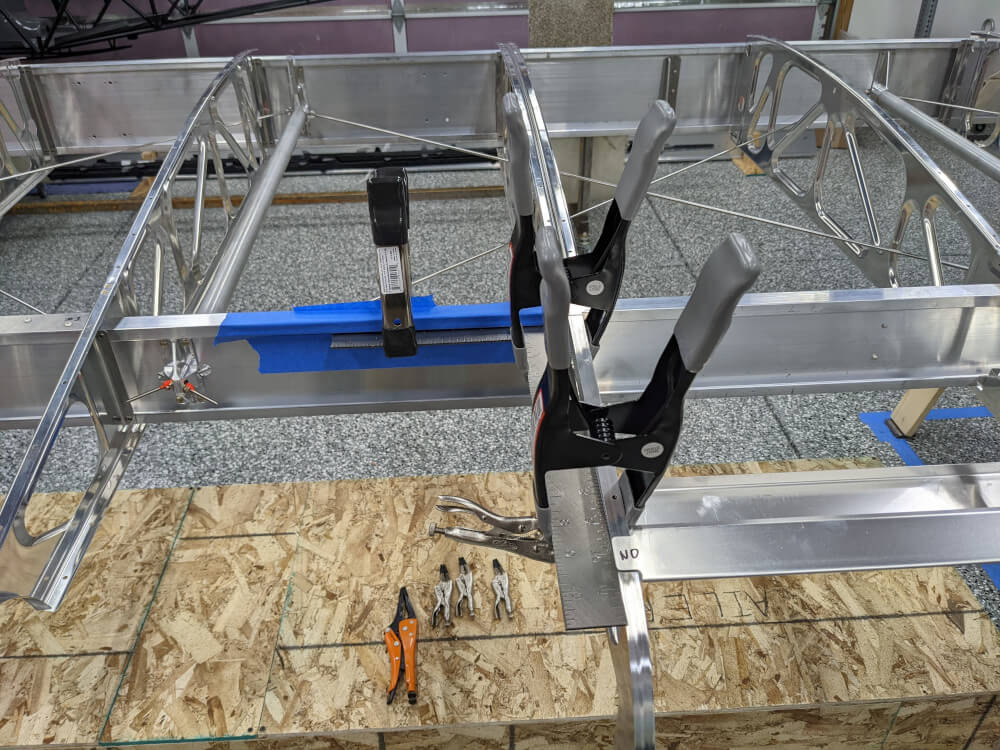 A framing square clamped to the flap/aileron hanger and the spar
Once this was done I slid the false spar side-to-side until the tabs used to attach it to the flap/aileron hanger overhung by a small amount (this is what it looked like they did in the manual) and there was a bit of a gap between the hanger and the false spar. I clamped it in place here to prevent movement. I also wrote “No” on the false spar in Sharpie in all of the places that I wasn’t supposed to drill yet in order to try to prevent myself from accidentally doing so when I got into a groove.
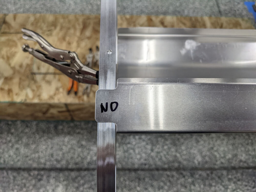 The flap false spar lines up on the flap/aileron hanger
The manual then specified that all of the tail ribs should be square to the spar so I used a variety of sizes of machinist squares to try to make sure that they were. I adjusted the tail ribs until they were as square as I could get them, made sure the false spar was fully pushed on over them, and then clamped them in place (top and bottom). I went back and forth doing this several times for each rib and probably went a bit overboard with it but I do think the end result was pretty good. I had originally used long nose locking pliers to clamp the false spar into place on the top and the bottom but discovered when it came time to drill that they got in the way. Instead I switched them out for cleco clamps right before drilling which worked well.
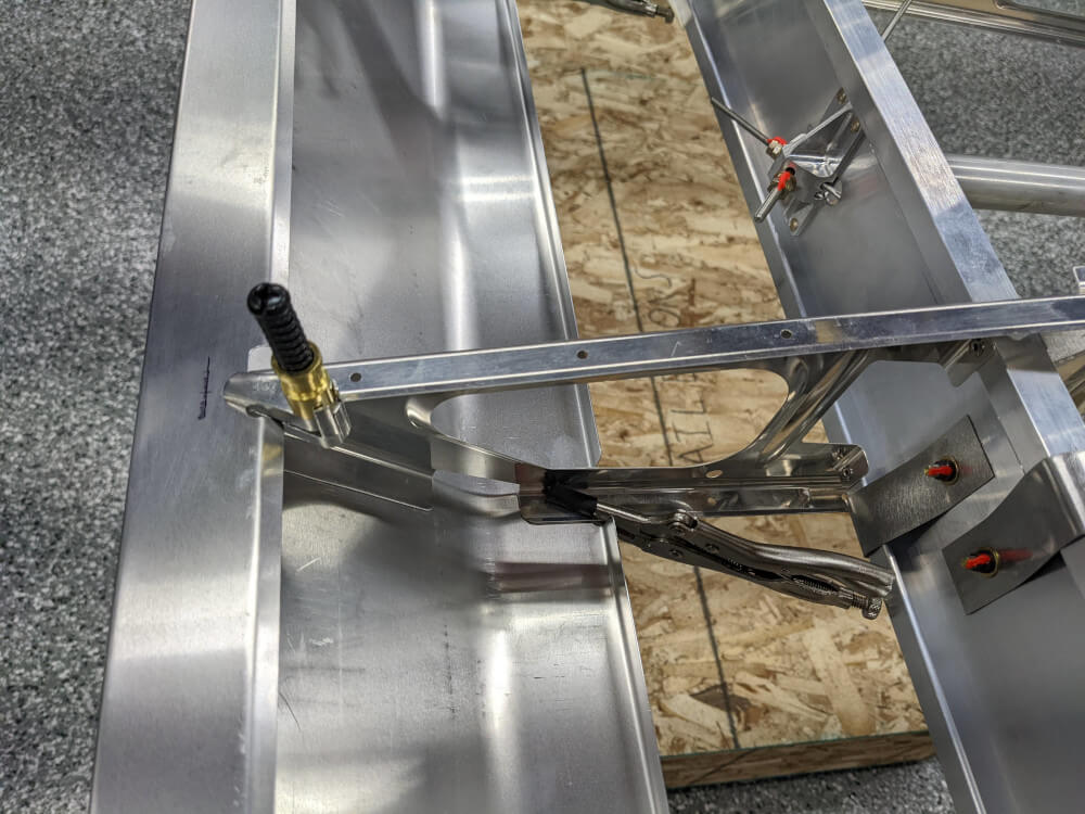 The false spar clamped to a tail rib and ready to be drilled
The manual said to do the main ribs (tail rib connected to a center rib) first and to start with the top holes. It also said to work from inboard to outboard. It wasn’t completely clear but since the top hole wasn’t supposed to be drilled for tail rib #1 I started with #3 (the most inboard other than #1 that is attached to a center rib) and drilled the top hole. I then proceeded in the following pattern with the holes numbered from top-to-bottom: hole 1, rib 4; hole 1, rib 2; hole 2, rib3; hole 2, rib 4; hole 2, rib 2; hole 3, rib 3; hole 3, rib 4; hole 3, rib 2; hole 4, rib 3; hole 4, rib 4; hole 4, rib 2; hole 2, rib 1; hole 3, rib 1. This seemed to work well.
Before drilling each hole I made sure one more time that the rib was square, pushed all the way into the false spar, and clamped in place. I then carefully marked the position of the hole and centre punched it to try to create a spot for the drill bit to get started without wandering too much. I made sure to have a block of wood behind the spot I was center punching to prevent creating a large dent in the sheet metal. I then drilled the hole with a #30 bit as carefully as I could. The top and bottom holes were drilled from outside to inside using jobber length bits but the inside holes were drilled with a 6” bit so that I could ensure I was going through the tail rib appropriately while still fitting the drill (vs. a shorter bit). Each hole received a cleco after being drilled.
With all of the tail ribs drilled and cleco’d, I drilled the holes for the 2 rivets in the aileron/flap hanger that are supposed to be installed during this step. I made sure to measure their locations carefully and drilled with a #40 bit first to create a pilot hole before enlarging with a #30. I also drilled the hole for the bottom rivet from the bottom (after measuring carefully) instead of from the top per Craig’s advice since it is easier to reach and there is less in the way.
Finally, I deburred all of the holes and installed rivets. One change I made to the manual here, once again at Craig’s suggestion, was to use a CCP-43 stainless steel rivet in the bottom hole instead of the SS/SS42D rivet called for. This is the equivalent rivet with the exact same specs but one size up (in length) and made by Cherry Aerospace. We did this because the maximum grip range of the SS/SS42D rivets is 1/8” and the hanger in that position was 1/8” thick. Since it was also going through the sheet metal it was slightly too short of a rivet for this part. I’m sure the manual still calls for the SS/SS42D rivets because it is close enough and not very structural but it was easy to get the appropriate rivets and was nice to officially stay within their installation specs. With the installation of these rivets section 221 of the manual, was officially complete!
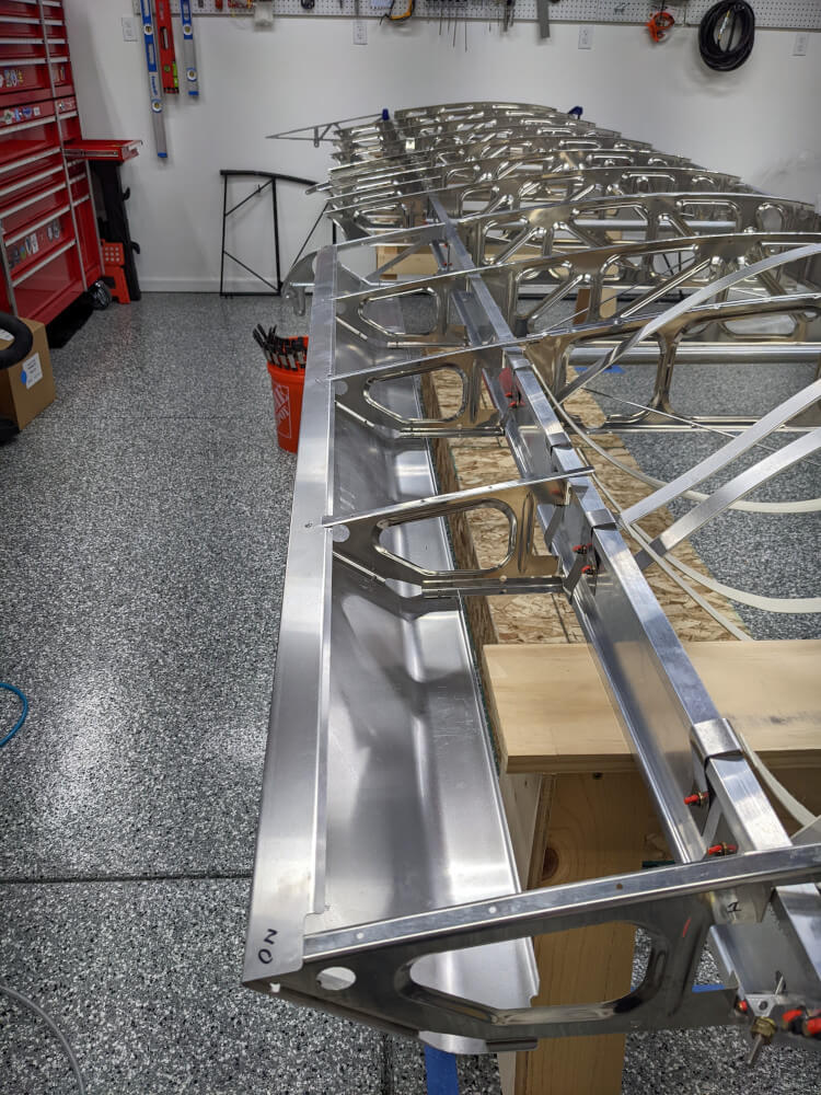 The flap false spar fully installed
Wing Manual (Extended Fuel), CCEX-004 Rev. 2.02, Pages 103-105 ↩