Trammeling
Craig came back today to help finish up the steps we mostly completed yesterday and to get a bit more done. We started by adding Loctite 721 to each of the jam nuts on the drag wires and snugging them in place. We also marked each of the nuts that we Loctite’d with torque seal in order to keep track of which ones were done and to make a visual inspection easy to complete. The only exception to this is that we didn’t Loctite the nuts on the inboard ends of the bay 1 drag wires since they will need to be removed later in order to install the fuel tanks.
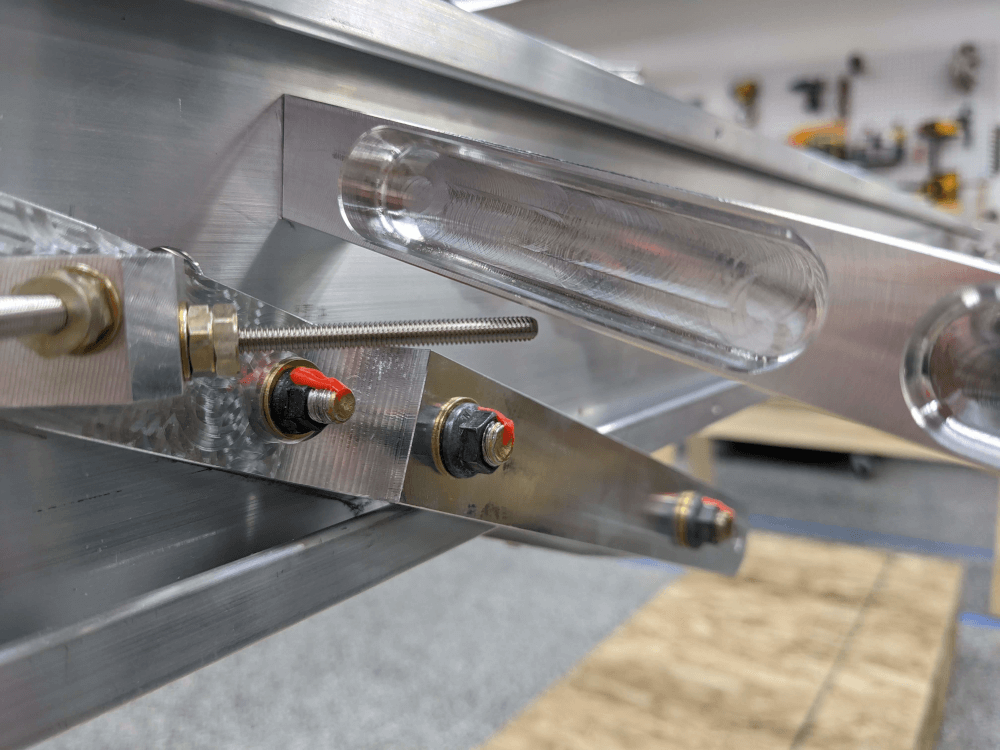
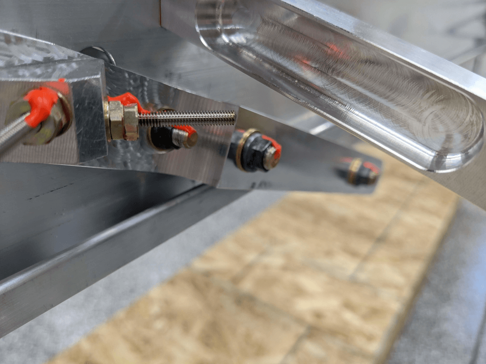
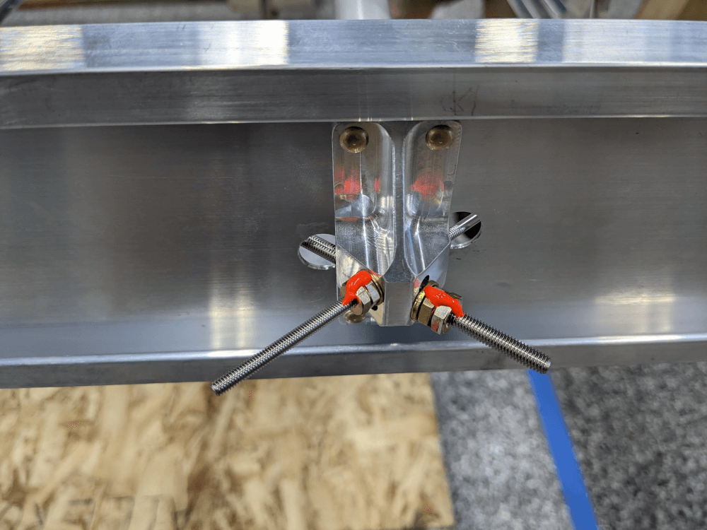 Drag wire jam nuts secured with Loctite and torque sealed
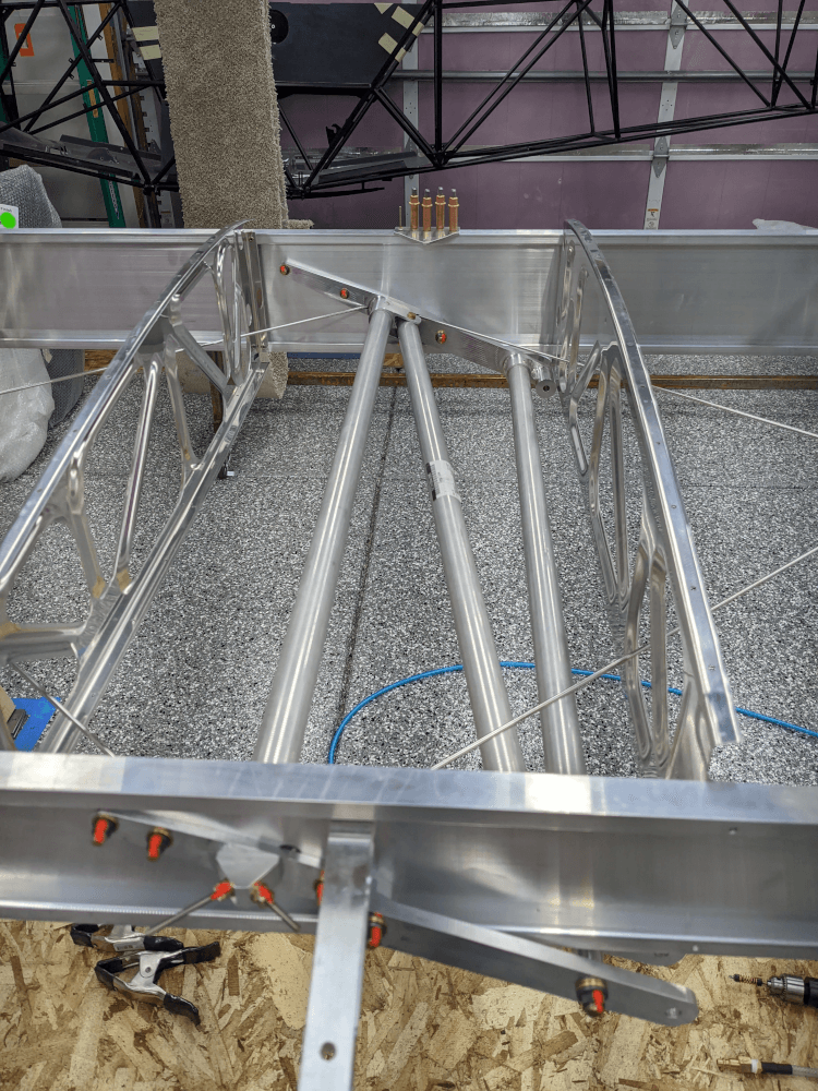
Instead, I measured the length of the drag wires extending beyond the fittings using my digital calipers and wrote these values on the spar. Later, when these wires are reinstalled through the fuel tank, they can be re-tightened until the same amount of wire is protruding. This will provide the same tension and ensure that the first bay of the wing stays square. At this point, the trammeling step1 was done.
Aileron Hanger
We also finished up section 162 of the manual from the previous day by trimming the drag wire closest to the center aileron hanger. It didn’t make contact but the clearance was a little closer than I would have liked and there was way more than enough wire protruding. I marked a position where a little over an inch of wire was sticking out and cut off the rest using a cutoff wheel on my Dremel tool. I also used a sanding drum attachment to smooth out the sharp edges. Dave Embry recommends cutting off the excess wire on all of the drag wires but we elected to leave the others as-is and trim them later only if clearances get a little too tight.
 Clearance between the drag wire and center aileron hanger before trimming
With the wire trimmed, I reinstalled the center aileron hanger using Loctite 721 on the bolt and torqued it to 25 in/lbs.
 The center aileron hanger installed with the final clearance from the drag wire
Diagonal Cross Tube
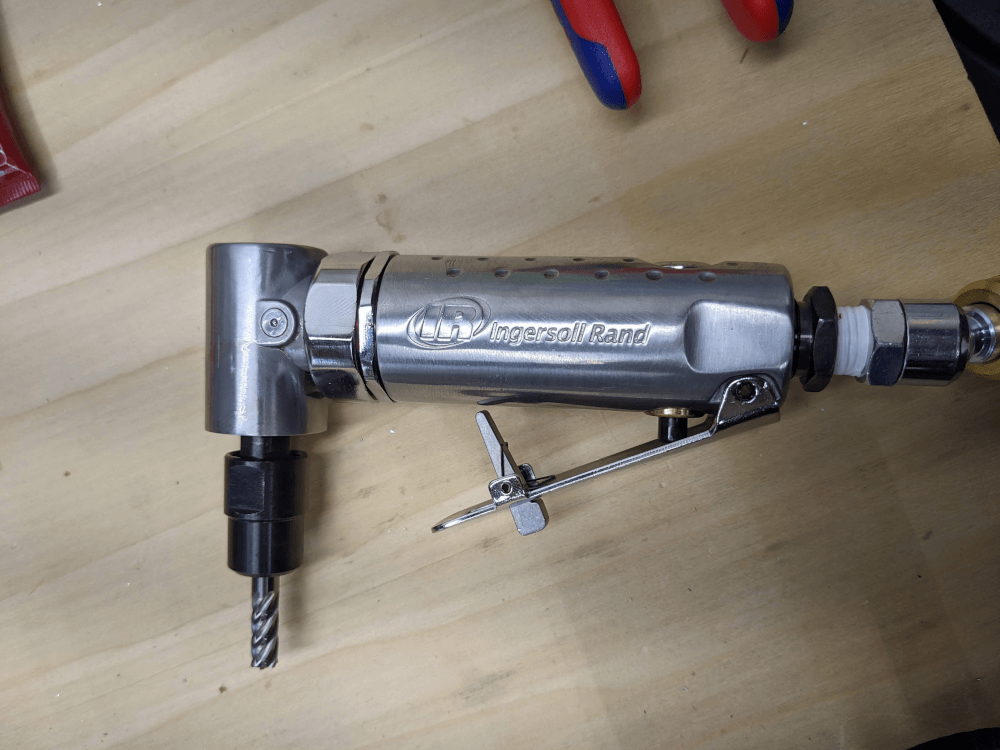
With the wing fully trammeled we moved on to section 173, installing the diagonal cross tube. This is another drag tube that fits between the lift strut fittings at an angle from inboard to outboard and top to bottom. In order to install it a section of the end must first be trimmed so that it will fit over a bolt head in the front spar fitting. I did this using a carbide burr meant for non ferrous metals (like aluminum) in my die grinder. This worked really well to remove large amounts of material quickly and let me get very close to the line I drew marking the edge of the cut. Once I was close, I finished up using a sanding attachment on the Dremel to smooth the cut out and some sandpaper to take off the sharp edges.
 The carbide burr used to trim the cross tube
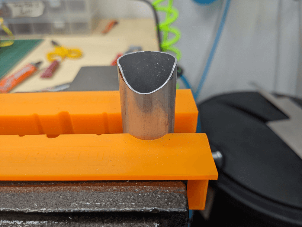 The diagonal cross tube after being trimmed
Now that the cross tube was ready we placed it in position and Craig held it while I match drilled the first hole using a #12 drill bit. I then inserted a short (AN3-3A) AN3 bolt to keep everything lined up so that I could match drill the bottom. Once that was done I inserted a long AN3 bolt (the AN3-14A bolt that you are meant to use here) to keep that end lined up and repeated the process for the other side.
After the holes were match drilled we removed the tube to deburr the inside of the holes and then reinstalled it using the correct hardware. The manual mentions that these bolts don’t need to be torqued (just snug) but there is an answer on the forums that talks about how 20-25 in/lbs is basically just snug anyway. Mitch (former builder assist manager) responded that the factory used 28-30 in/lbs for these bolts. Since 20-25 in/lbs is the spec for AN3 bolts and agrees with the bolts being snug that is the torque value we used.
 The diagonal cross tube fully installed
Front Pulley Bracket
Next we moved on to section 184 - installing the front pulley bracket. The position of this bracket is fairly important because it holds an aileron pulley cable and because it is riveted into the spar cap and a misplaced hole could damage the spar. The manual calls for it to be placed 4 5/8” outboard from the #8 rib so we carefully measured using a ruler and then confirmed with the digital calipers. With the bracket clamped in place using a couple of spring clamps we ensured that the holes would fall into the safe section of the spar and double checked the measurement from the #8 rib. We also made sure that the front of the bracket was flush with the front of the spar (as far as we could feel with our fingers) since this confirmed that it was in the right place and the holes would be drilled correctly.
From there, I drilled the holes using a #30 bit and a drill stop. I installed a cleco after each hole and removed the spring clamps after three out of the total 5 were done since the clecos would hold just fine. As I went I also deburred the back of the holes which was a bit of a challenge due to the location in the inside of the spar cap. I was eventually able to reach all of the burrs using a combination of dental picks, pieces of broken paint stirrers, and a few other tools.
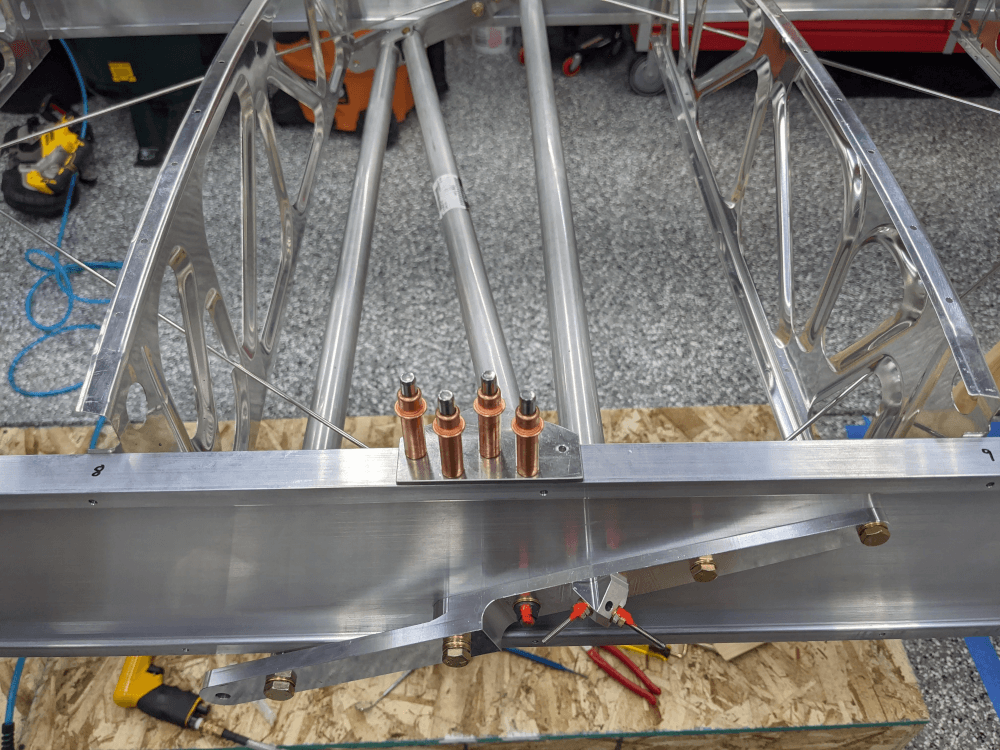 The front pulley bracket cleco’d in place
All that is left to do to complete this step is to insert and pull the CherryMAX rivets used here. We opted not to do that yet because the spar bulbs prevent the rivets from being fully inserted into the holes and we want to practice a few test rivets in some scrap to get the technique down before trying it on the plane. Hopefully the rivet will pull easily (like the machined tail rib rivets that didn’t quite insert all the way) and this step will be completed quickly.
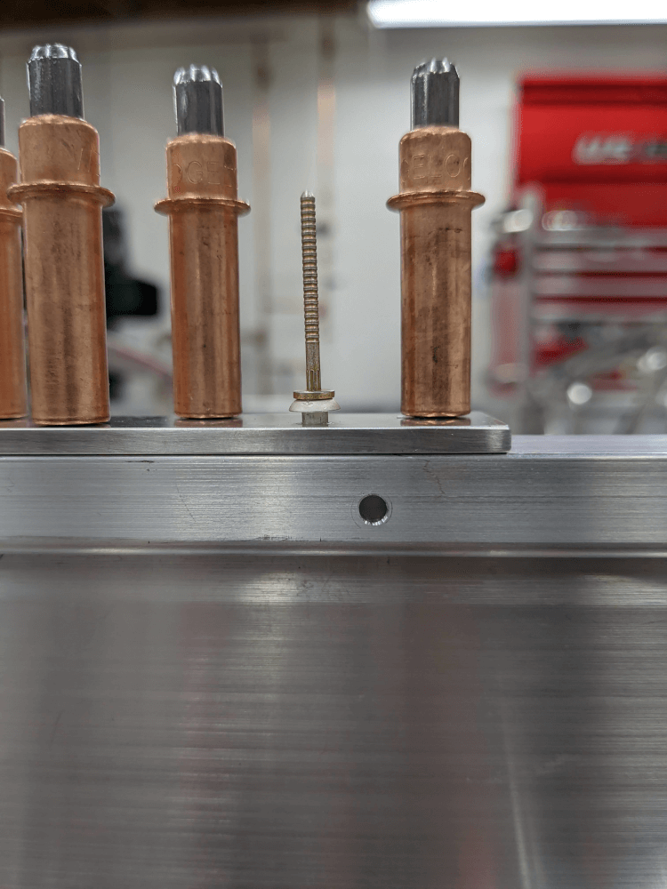 Pulley bracket rivet unable to be inserted all the way
Rear Pulley Bracket
Finally, I tried assembling the rear pulley bracket per figure W28 on page 97 of the manual to get it ready to be installed and to help align the rear spar reinforcement in the next steps. Unfortunately, when I did this I discovered that the holes in the bracket didn’t seem to line up correctly and that the pulley didn’t sit parallel to the sides.
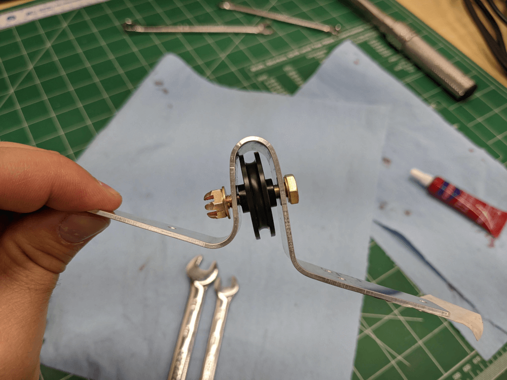 The rear pulley bracket not lined up correctly
I was able to tighten the bolt town all the way with one side of the bracket clamped to the table in order to make everything parallel. Unfortunately, this meant that the pulley did not turn and that the bracket didn’t sit flat without some sort of clamp holding it down. The rivets that attach it could provide the clamping force but this doesn’t seem quite right so I posted a question to the builder’s Facebook group asking for some clarification.